Multishaft synchronous servo driving system and synchronous control method thereof

A servo-driven, multi-axis synchronization technology, which is applied in the direction of multiple motor speed adjustments, can solve the problems of low execution effect, low cost performance, and separation from centralized control methods, and achieve the effects of enhanced synchronization, high cost performance, and improved performance

Inactive Publication Date: 2011-07-20
NANJING SHOWMOTION MECHATRONICS TECH
View PDF8 Cites 31 Cited by
  • Summary
  • Abstract
  • Description
  • Claims
  • Application Information

AI Technical Summary

Problems solved by technology

[0004] The errors existing in the above multi-axis servo drive system will affect the processing accuracy of the multi-axis servo drive system to a certain extent
[0005] After searching, it is found that the Chinese patent with the publication number CN101038491A discloses a "Self-synchronized AC Servo System Cooperating with High-speed Serial Communication". The problem in this system is : 1) The system is based on high-speed serial communication and deviates from the centralized control mode, so it cannot improve the performance of the existing mainstream centralized multi-axis system; The system puts forward very high requirements, and a real-time operating system must be used, otherwise the real-time performance of sending serial data cannot be guaranteed; at the same time, high requirements are also put forward for the servo drives of each axis in the lower layer, and each axis servo drive needs to increase high-speed, high-performance and high-cost devices, and the final execution effect is still lower than the traditional centralized control method; 3) The synchronization signal sent by the main axis servo driver of the system must be high-speed continuous, and other slave axis servo drivers rely on synchronization every moment Signal to execute every step, wrong step by step, increases the risk of using the system
Comprehensive analysis of cost, reliability, operation effect, etc., the current Chinese patent system of CN101038491A is less cost-effective than the centralized control method

Method used


Image

  • Multishaft synchronous servo driving system and synchronous control method thereof
  • Multishaft synchronous servo driving system and synchronous control method thereof
  • Multishaft synchronous servo driving system and synchronous control method thereof

Examples


Embodiment

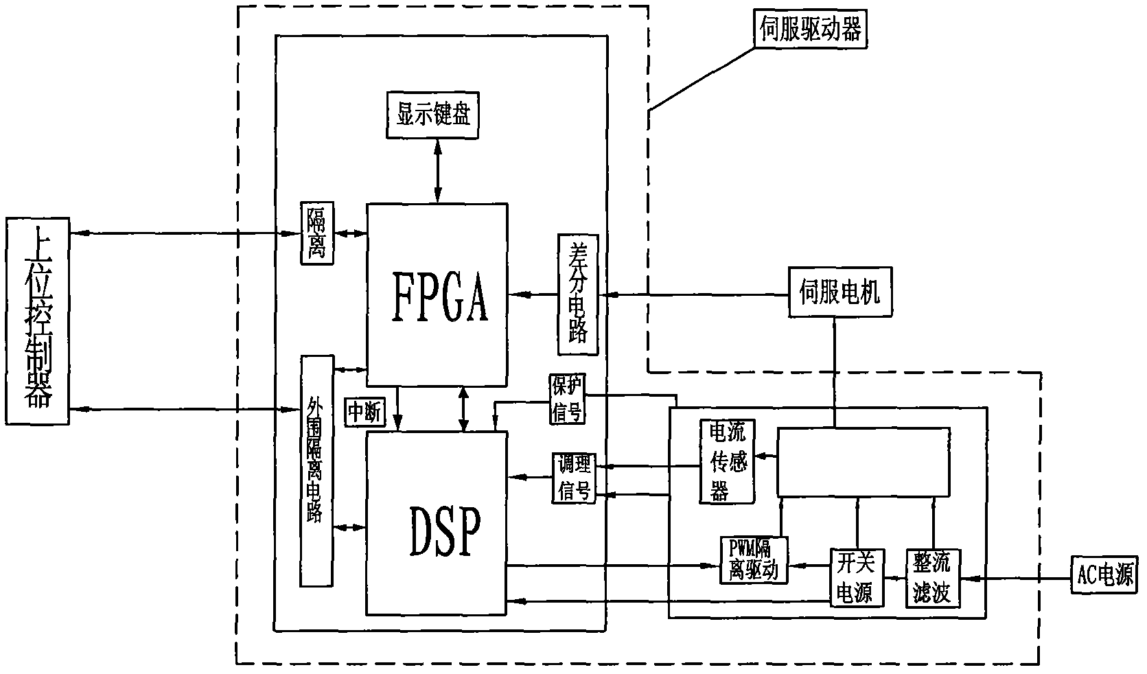
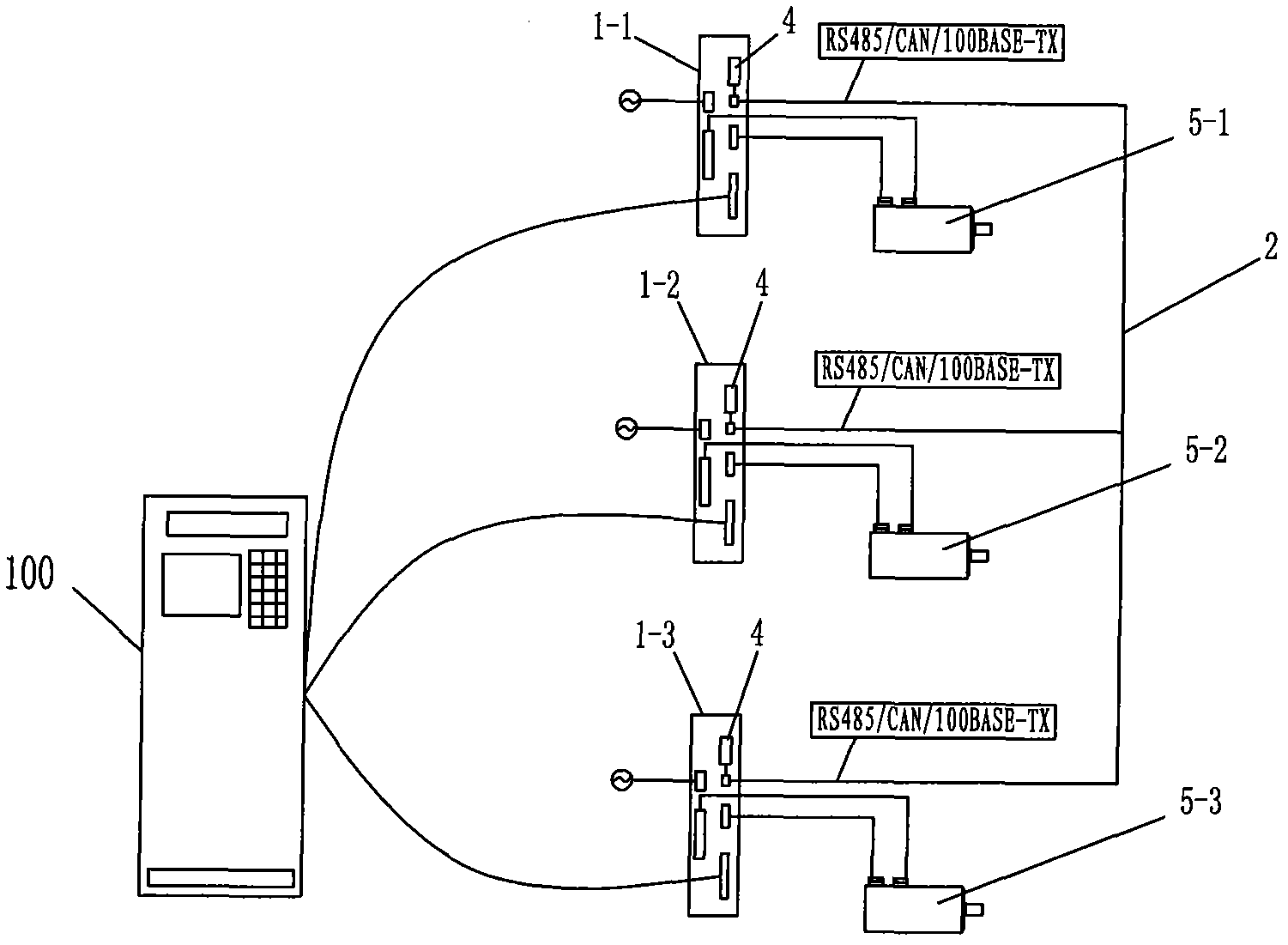
[0033] The multi-axis servo drive system of this embodiment is as image 3 As shown, it includes a host controller 100, three servo drivers 1-1, 1-2, 1-3 and three servo motors 5-1, 5-2, 5-3. This embodiment selects three a servo drive. The servo drive generally contains FPGA unit, DSP unit, current loop control loop unit, speed loop control loop unit, position loop control loop unit and auxiliary circuit; the input end of the servo drive is connected to the host controller, and its output end is connected to the servo drive. motor. All of the above are prior art, and other prior art will not be repeated here.

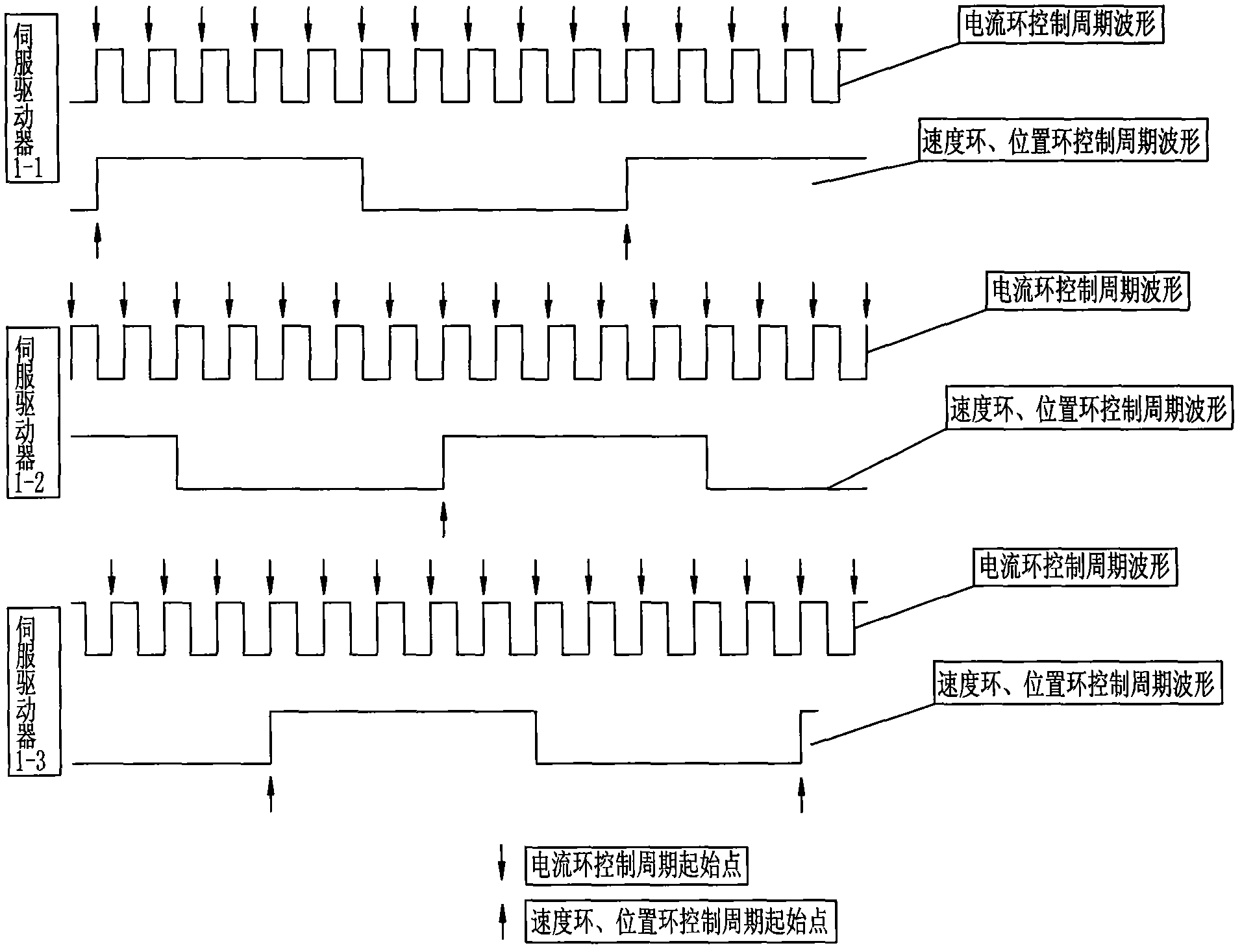
[0034] Three servo drives 1-1, 1-2, 1-3 all contain Synchronous interrupt processing module 4 and the three servo drives 1-1, 1-2, 1-3 are connected to each other with a synchronous communication bus 2, and one of the servo drives 1-1 is to connect it Synchronous interrupt processing module 4 is set to regularly send synchronous signals to the synchronous communi...


PUM


Abstract

The invention relates to a multishaft synchronous servo driving system and a synchronous control method thereof, and belongs to the technical field of control systems. In the system, any one of servo drivers is selected as a main servo driver for regularly sending a synchronous signal to synchronous communication buses, and the others are used as auxiliary servo drivers; the synchronous communication buses are connected among the servo drivers; and a synchronous interruption processing module is arranged in each servo driver. The method comprises the following steps of: regularly sending the synchronous signal from the synchronous interruption processing module of the main servo driver, generating the highest priority level on the auxiliary servo drivers so as to shield interruption, modifying a control period length set value of current loops of the auxiliary servo drivers by the synchronous interruption processing modules of the auxiliary servo drivers, and zeroing the execution frequency of the current loops in a speed loop. By the system and the method, the error among the control period lengths of the control loops of the servo drivers can be reduced greatly within a synchronous interruption interval, so the synchronism of the system is enhanced greatly, and the processing precision of the system is guaranteed.

Description

technical field [0001] The invention relates to a servo drive system and a method for controlling the synchronization of the servo drive system, belonging to the technical field of control systems. Background technique [0002] The servo drive system is a digital discrete closed-loop control drive system, and its basic components are the host controller, servo drive and servo motor. The basic composition of the existing servo drive is as follows: figure 1 Shown, including FPGA (Field-Programmable Gate Array, Field Programmable Gate Array) unit, DSP (Digital Signal Processor Digital Signal Processing, referred to as DSP)) unit, current loop, speed loop and position loop control loop unit and auxiliary Circuit, DSP contains PWM (Pulse Width Modulation, pulse width modulation) timer, PWM timer contains three basic units - period register, comparison register, counting register, of which the period register and comparison register have shadow registers. In specific use, the se...

Claims


Application Information

Patent Timeline
Patent Type & Authority Applications(China)
IPC IPC(8): H02P5/50
Inventor 柳德伟刘剑东
Owner NANJING SHOWMOTION MECHATRONICS TECH
Why Eureka
Try Eureka