Ultra wide band electromagnetic band gap structure for suppressing ground bounce noise of high speed circuit/microwave circuit

An electromagnetic bandgap, broadband technology, applied in circuits, printed circuit components, electrical components, etc., can solve problems such as damage to power integrity, achieve good power integrity, achieve power integrity, and suppress ground bounce noise.

Inactive Publication Date: 2011-07-20
NANJING UNIV
View PDF4 Cites 11 Cited by
  • Summary
  • Abstract
  • Description
  • Claims
  • Application Information

AI Technical Summary

Problems solved by technology

In the microwave frequency band, in addition to inductive components, the resonance of the circuit board itself becomes a more important cause of ground bounce noise. At certain resonant frequencies, the current change of a chip will easily propagate in the circuit board, causing other Variations in chip supply voltage, thereby compromising overall system power integrity

Method used


Image

  • Ultra wide band electromagnetic band gap structure for suppressing ground bounce noise of high speed circuit/microwave circuit
  • Ultra wide band electromagnetic band gap structure for suppressing ground bounce noise of high speed circuit/microwave circuit
  • Ultra wide band electromagnetic band gap structure for suppressing ground bounce noise of high speed circuit/microwave circuit

Examples


Embodiment Construction

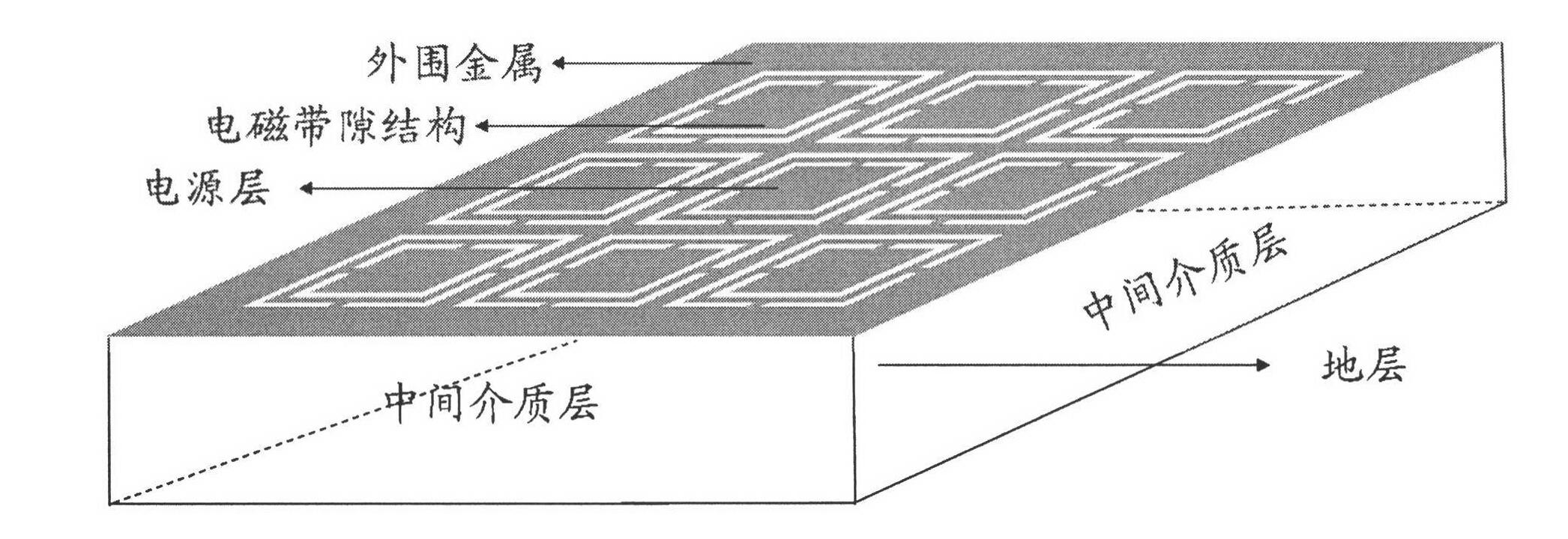
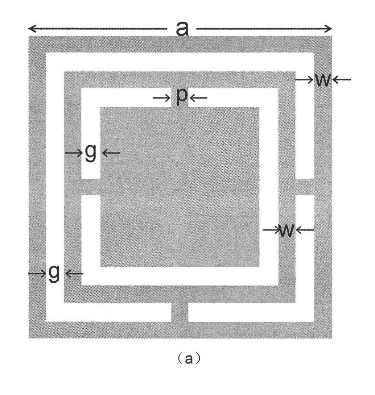
[0010] Firstly, a sample with a three-layer structure as proposed in the technical scheme needs to be prepared. The middle is a dielectric plate, the material can be selected such as polytetrafluoroethylene, FR4, Roger series and other dielectrics, the upper and lower layers are copper-clad, one side is continuous, and the other side needs to be etched into such as figure 2 electromagnetic bandgap structure.

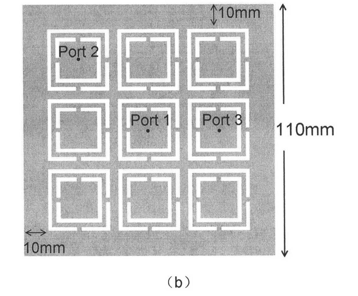
[0011] After the processing is completed, it needs to be verified by specific experiments. When it is confirmed that it can achieve an insertion loss lower than -30dB for any two ports in a certain frequency band, it can be used as an ordinary high-speed circuit / microwave circuit. Replacement of power planes for suppression of ground bounce noise.


PUM


Abstract

The invention provides a novel ultra wide band electromagnetic band gap structure which belongs to the technical field of information. The structure is mainly used for replacing a power layer of the traditional high speed circuit / microwave circuit so as to suppress ground bounce noise in the structures and realize better power integrity. The structure has a typical three-layer circuit board structure comprising a dielectric layer in the middle and two metal layers up and down, wherein the electromagnetic band gap structure is arranged on the upper layer. In the invention, a typical example is verified, i.e. a sample prepared in an experiment is tested through a network analyzer, which confirms that the structure provided by the invention can realize noise suppression superior to -30dB to any two ports in a frequency range from 500MHz to 5.5GHz.

Description

Technical field: [0001] The invention relates to a novel ultra-broadband electromagnetic bandgap structure, which belongs to the field of information technology. Its main purpose is to replace the power supply layer of the existing high-speed circuit / microwave circuit, thereby suppressing the ground bounce noise existing in these structures, and realizing better power integrity. Background technique: [0002] Now electronic technology, especially chip and packaging technology is gradually having the characteristics of high speed, dense integration, low power consumption, etc., and its demand for power integrity is also increasing. Due to the low working frequency band of traditional circuit boards, the power supply system generally uses ordinary power lines for power supply, and the ohmic loss is also very small, so it has very good power integrity. However, with the gradual increase in the operating frequency band of electronic devices such as processors and memory, the oh...

Claims


Application Information

Patent Timeline
Patent Type & Authority Applications(China)
IPC IPC(8): H05K1/02H01P1/203
Inventor 徐晓非冯一军凡金龙黄慈张欢赵俊明
Owner NANJING UNIV
Why Eureka
Try Eureka