Rolling bearing arrangement and wind turbine equipped therewith

A technology of wind power generation equipment and rolling bearings, applied in wind power generation, bearings, ball bearings, etc., can solve problems such as wear, large expenditure, and single rolling element stuck

Inactive Publication Date: 2011-07-20
IMO HOLDING GMBH
View PDF9 Cites 10 Cited by
  • Summary
  • Abstract
  • Description
  • Claims
  • Application Information

AI Technical Summary

Problems solved by technology

However, the disadvantage is that, instead of a single cage, a large number of smaller cage segments each having only two receiving pockets for the rolling elements have to be used, which is precisely the case with sizes having a diameter of approximately 1000 mm or more. Larger rolling bearings lead to greater outlay in assembly
In addition, cage segments that are only

Method used


Image

  • Rolling bearing arrangement and wind turbine equipped therewith
  • Rolling bearing arrangement and wind turbine equipped therewith
  • Rolling bearing arrangement and wind turbine equipped therewith

Examples


Embodiment Construction

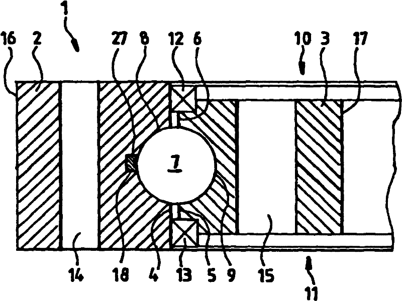
[0047] The rolling bearing 1 shown as an example in the drawing is used for the rotatable connection of a first plant or machine part to a foundation or a second plant or machine part. For this purpose, the rolling bearing 1 has two annular connecting elements 2 , 3 .

[0048] through according to figure 1 The cross-section of the rolling bearing 1 makes the internal structure of the rolling bearing 1 recognizable. A typical construction of a radial bearing can be identified, wherein the first connecting element 2 is designed as a planar outer ring (connecting element 2 in figure 1 can be seen on the left side of the center), while the second connecting element 3 is configured as an inner ring 3 concentrically arranged in the outer ring 2 ( figure 1 center on the right). The two connecting elements 2 , 3 each have an approximately rectangular cross section. Between the inner casing 4 of the outer connecting element 2 and the outer casing 5 of the inner connecting element 3...


PUM


Abstract

The invention relates to a rolling bearing arrangement comprising two concentric rings, at least sections of which are arranged inside one another and comprising a gap between said rings, allowing the latter to rotate in opposition to one another about an imaginary axis in the centre of the rings that runs approximately perpendicularly to the ring plane. A race for at least one row of rotationally symmetrical rolling bodies that roll between the rings is situated in the vicinity of a gap section between the rings that surrounds the rotational axis at a constant radius, said race forming a closed loop on one plane. The rolling bodies in one row are guided through a cage at approximately equidistant intervals, said cage having at least one disc-shaped region set into a continuous circular groove-type depression in the vicinity of the race of a bearing ring and a comb-type form with a plurality of spacer pieces that are interconnected in combination along a back region, each piece having a pocket formed between neighboring spacer pieces for receiving a respective rolling body, the opening of each pocket extending continuously in the upper face of the cage beyond the edge of said cage lying opposite the back region into the lower face. According to the invention, the cage is completely interrupted in at least one place and formed from a resilient material, so that it can be bent up and/or together in the region of the approximately disc-shaped region. The invention further relates to a wind turbine equipped with said bearing arrangement.

Description

technical field [0001] The invention relates to a rolling bearing arrangement, in particular in the context of a (drivable) rotary connection, and to a wind power plant equipped with at least one such rolling bearing, preferably for main bearings, transformers, etc. of a wind power plant. A paddle bearing and / or a yaw bearing having two annular connecting elements arranged concentrically with each other and at least partially staggered, and a gap between these connecting elements, so that these connecting elements can rotate around a virtual , axes approximately perpendicular to the plane of the ring, at the center of the connecting elements, rotate relative to each other, wherein at least one in-plane An inner circular closed raceway for at least one row of rolling bodies each of rotationally symmetrical configuration rolling between the connecting elements, wherein the rolling bodies are guided in rows at approximately equal intervals by means of a cage, the retaining The c...

Claims


Application Information

Patent Timeline
IPC IPC(8): F16C33/38F16C33/41
CPCF16C33/3806F16C33/3818F16C2300/14F16C33/41F16C33/425Y02E10/721F16C19/16Y02E10/72
Inventor 弗兰克·胡贝图斯
Owner IMO HOLDING GMBH
Why Eureka
Try Eureka