Staged powder spraying entrained bed gasification furnace and gasification method thereof

A gasifier and entrained bed technology, applied in the field of clean utilization of carbon-containing fuels, can solve the problems of difficult gas-solid flow field, oxygen depletion of nozzles, short operation period, etc., to reduce high temperature sintering and fuel bonding, simplifying The effect of gasification nozzle structure and cost reduction

Inactive Publication Date: 2011-07-27
INST OF PROCESS ENG CHINESE ACAD OF SCI
View PDF5 Cites 23 Cited by
  • Summary
  • Abstract
  • Description
  • Claims
  • Application Information

AI Technical Summary

Problems solved by technology

Although there is a strong impingement flow in the multi-nozzle opposed entrained-bed pressurized gasification furnace, it is difficult to obtain a stable and uniform gas-solid flow field in the furnace due to the hedging arrangement, and the nozzles are in an oxygen-poor state, and the service life is limited. limit
Because ...

Method used


Image

  • Staged powder spraying entrained bed gasification furnace and gasification method thereof
  • Staged powder spraying entrained bed gasification furnace and gasification method thereof
  • Staged powder spraying entrained bed gasification furnace and gasification method thereof

Examples


Embodiment 1

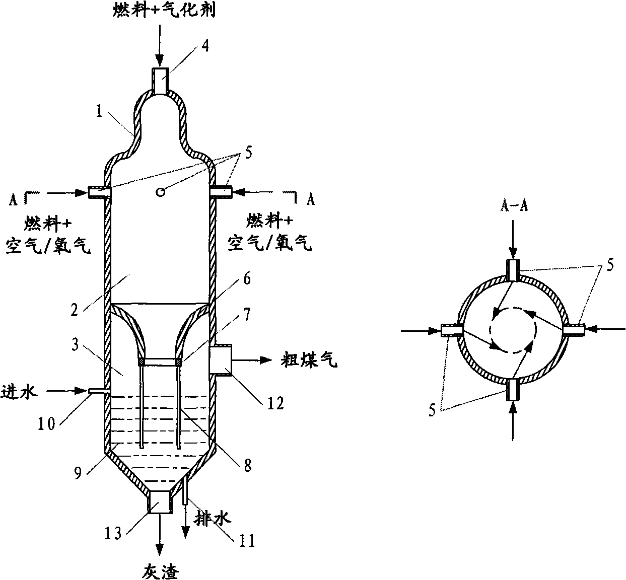
[0045] The entrained bed gasifier 1 of the semicircular dome, non-equal cross-section, and four combustion nozzles arranged along the gasifier is as follows: figure 1 As shown, it includes: gasification chamber 2 and chill chamber 3.

[0046] The gasification chamber 2 is circular in section, the upper section of the gasification chamber 2 is small, the lower section is large, and has a semicircular dome. The gasification chamber 2 includes a gasification nozzle 4, four combustion nozzles 5, a gasification Room Exit 6. The gasification nozzles 4 are located on the semicircular dome of the gasification chamber 2 , and the combustion nozzles 5 are symmetrically distributed along the cross section of the gasification chamber 2 on the upper part of the gasification chamber 2 . The axis of the gasification nozzle 4 in the gasification chamber 2 coincides with the axis of the gasification chamber 2, and the section formed by four combustion nozzles 5 distributed symmetrically along...

Embodiment 2

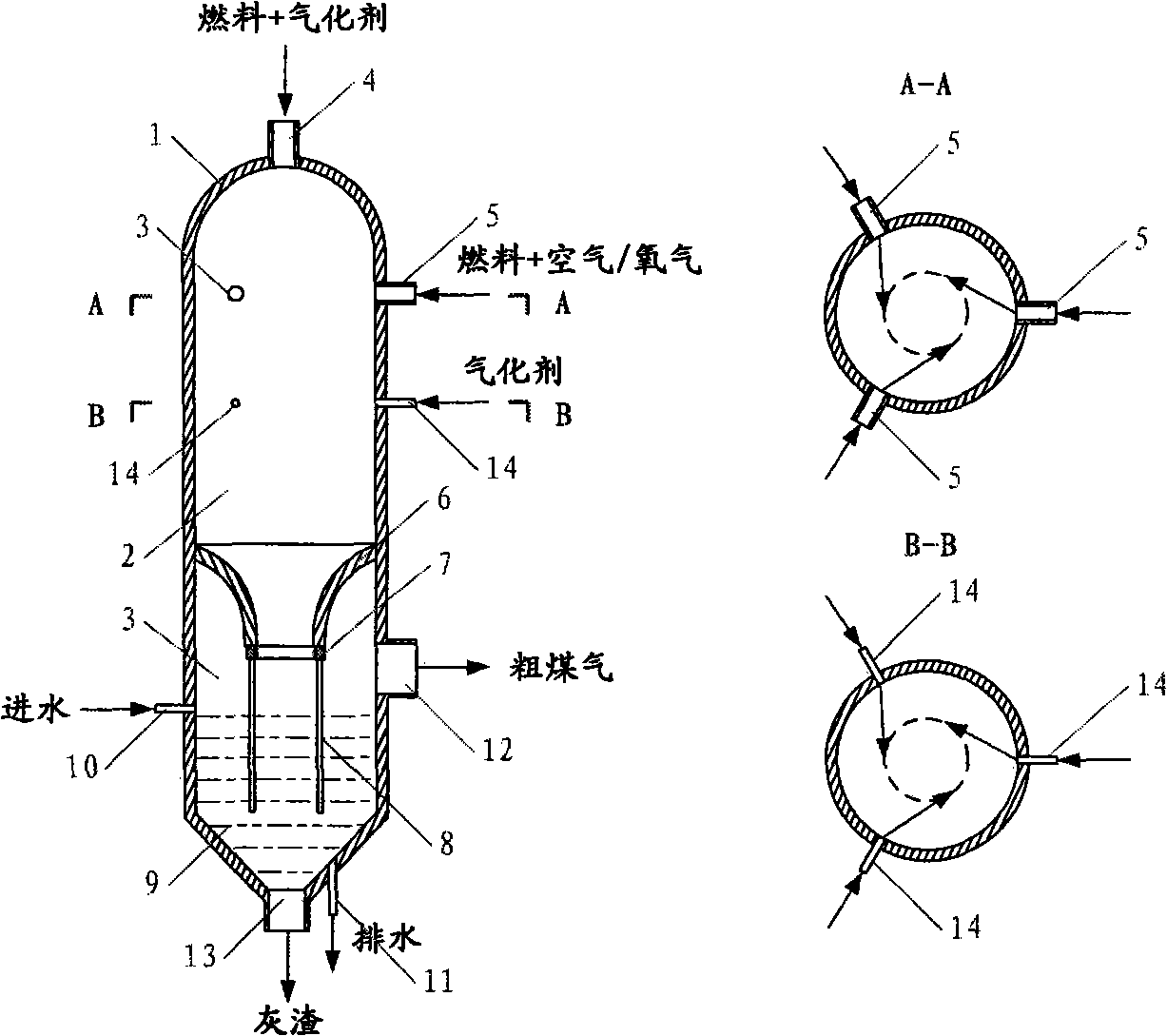
[0051] The entrained bed gasifier 1 of the semicircular dome, equal section, and three combustion nozzles arranged along the gasifier in this embodiment is as follows: figure 2 shown. Different from Embodiment 1, the gasification chamber 2 in this embodiment is a gasification chamber with equal cross-section, and there are three combustion nozzles 5 arranged in the gasification chamber 2, which are evenly arranged along the cross-section of the gasification chamber 2 . In addition, three gasifying agent replenishment ports 14 are arranged below the combustion nozzle 5 , arranged at the same angle as the combustion nozzle 5 , and the cross-sectional axis of which is perpendicular to the axis of the gasifier 2 .

[0052] The difference from Example 1 is that during the gasification process, the mixture of fuel and air / oxygen used for preheating combustion is sprayed at a certain angle (along an imaginary tangential circle in the gasifier) ​​from three combustion nozzles 5 respe...

Embodiment 3

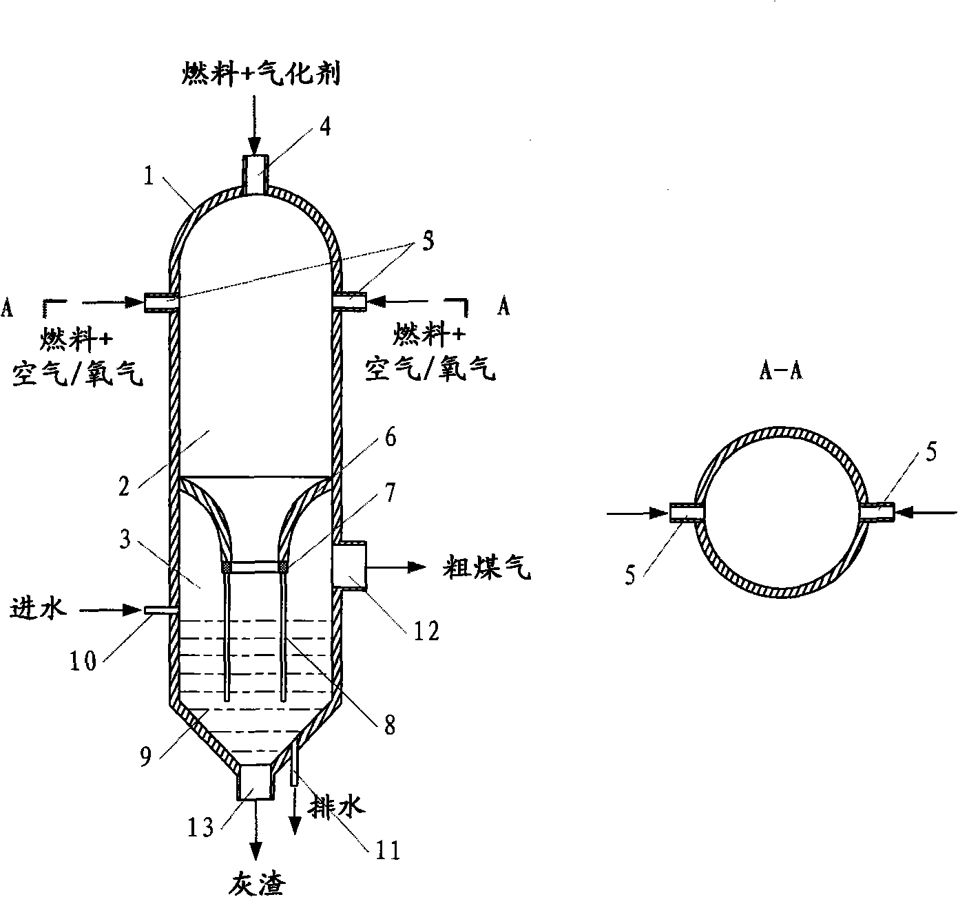
[0054] The entrained bed gasifier 1 of the semicircular dome, equal cross-section, and two combustion nozzles arranged opposite to each other in this embodiment is a step-by-step powder spraying entrained bed gasifier 1 such as image 3 shown. The difference from Example 1 is that the gasification chamber 2 used in this embodiment is a constant-section gasification chamber, and two combustion nozzles 5 are arranged on the upper part of the gasification chamber 2. The axis of furnace 2 is vertical.

[0055] During the gasification process, the fuel used for preheating combustion and the mixture of air / oxygen are sprayed and burned from the two combustion nozzles 5 respectively, forming strong disturbance and impact above the gasifier, increasing the gas-solid gap. mass and heat transfer between them.


PUM


Abstract

The invention relates to a staged powder spraying entrained bed gasification furnace, which comprises a gasification chamber and a quench chamber, and is characterized in that: the gasification chamber also comprises a gasification nozzle which is formed on the top of the gasification chamber and of which the axis is overlapped with the axis of the gasification chamber; the gasification chamber also comprises a plurality of combustion nozzles which are uniformly arranged on the upper wall of the gasification chamber along the upper periphery of the gasification chamber, and of which the axes form an angle of 0-90 degrees with the axis of the gasification chamber. The invention also relates to a method for gasifying powdery solid fuel in the gasification furnace. One part of fuel is sprayed together with an oxidant into the gasification chamber through the combustion nozzles, and is combusted, and a high temperature area is formed on the upper part of the gasification chamber; and the other part of fuel and a gasification agent are sprayed into the gasification chamber through the gasification nozzle, preheated on the top of the gasification chamber, and enters the high-temperature area for gasification. The service life of the nozzles can be effectively prolonged, the retention period of the fuel in the gasification chamber can be prolonged, higher carbon conversion rate can be achieved, and the gasification furnace can treat fuel with higher caking property.

Description

technical field [0001] The invention belongs to the technical field of clean utilization of carbon-containing fuels, and in particular relates to a staged powder-spraying entrained gasifier, in particular to a method for producing crude gas mainly composed of carbon monoxide and hydrogen by using powdered carbon-containing fuels, An entrained-bed gasification furnace with staged powder spraying, and a gasification method thereof. Background technique [0002] Gasification refers to a series of chemical reactions between the organic matter in the carbon-containing fuel (coal or biomass) and the gasification agent (such as steam / air or oxygen) under a certain temperature and pressure in a specific device, and the solid fuel Converted to CO, H 2 、CH 4 Process such as combustible gas. With the increasing shortage of natural gas and oil resources in the world, countries all over the world have carried out process development and industrialization research on the gasification o...

Claims


Application Information

Patent Timeline
IPC IPC(8): C10J3/56C10J3/54C10J3/72
Inventor 董利许光文郝江平高士秋汪印张聚伟
Owner INST OF PROCESS ENG CHINESE ACAD OF SCI
Why Eureka
Try Eureka