Plate type heat pipe with minitype circular channels

An annular channel, plate heat pipe technology, applied in indirect heat exchangers, lighting and heating equipment, etc., can solve problems such as hindering the return of liquid at the condensing end, restricting heat exchange efficiency, increasing heat transfer thermal resistance, etc. Burning performance, increasing the volume of the steam chamber, the effect of improving the heat transfer capacity

Active Publication Date: 2012-09-12
江乐新
View PDF0 Cites 0 Cited by
  • Summary
  • Abstract
  • Description
  • Claims
  • Application Information

AI Technical Summary

Problems solved by technology

However, this type of heat pipe generally requires the evaporation end to be on the bottom and the condensation end to be on the top. Its working principle is that the working fluid evaporates at the evaporation end and transfers the heat upward to the condensation end. At this time, the two phases of vapor and liquid move in the opposite direction at high speed in the same tiny channel, generating a large frictional shear force at the vapor-liquid interface, which will hinder the return of liquid at the condensation end, making the The heat transfer resistance is greatly increased, which restricts the heat exchange efficiency. When the heat flow is too large, the micro heat pipes will even be burned out. This situation has always been the bottleneck that restricts the further improvement of the comprehensive performance of the plate micro heat pipe clusters.

Method used


Image

  • Plate type heat pipe with minitype circular channels
  • Plate type heat pipe with minitype circular channels
  • Plate type heat pipe with minitype circular channels

Examples


Embodiment Construction

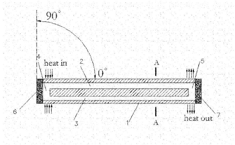
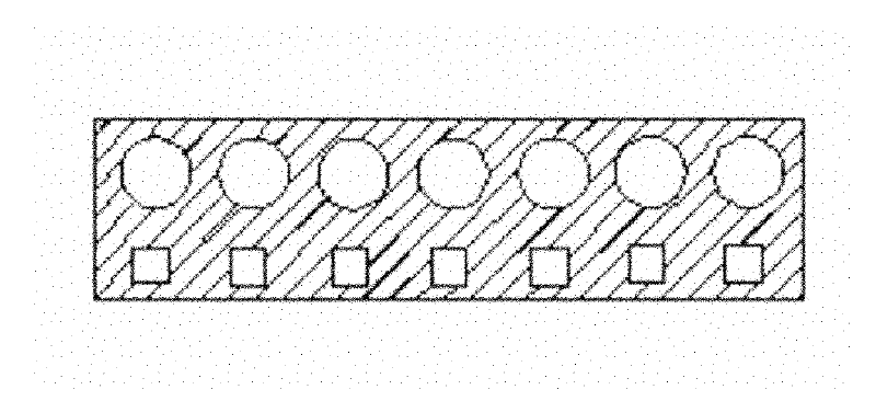
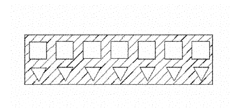
[0042] Such as figure 1 As shown, when the plate heat pipe is placed vertically (that is, the main channel is at a position perpendicular to the ground or working at a large angle), the steam chamber 5 is on the top, the liquid storage chamber 4 is on the bottom, the evaporation section absorbs heat, and the liquid storage chamber 4 The liquid working fluid that plays the role of phase change heat is heated and evaporated. Under the action of the pressure difference, the steam chooses to move to the condensation end through the evaporation channel 2 to transfer heat at a high speed. After the steam reaches the condensation end, the heat exchange is condensed into liquid, due to the return channel The capillary force of 3 is much greater than that of the evaporation channel 2. The liquid working medium basically flows back to the liquid storage chamber 4 under the action of the capillary force of the return channel 3 and gravity; when the evaporation channel 2 has a non-circular c...


PUM


Abstract

The invention relates to a plate type heat pipe with minitype circular channels. The interior of the plate type heat pipe is composed of a group or more than one group of minitype circular channels, wherein each circular channel comprises main channels and a connecting channel which is communicated with two ends of the main channels; the main channels are respectively an evaporation channel and abackflow channel; the connecting channel is respectively a liquid storage chamber and an evaporation chamber; the channels are filled with working media which play a role in phase change and heat transfer at a certain ratio, so that the efficient heat transfer of the heat pipe is realized; and welding, cold compression, hot compression or cementing are adopted for the sealing at each channel opening. The plate type heat pipe provided by the invention has the advantages of low heat resistance, high heat exchange efficiency, light weight, simple structure, high bearing capability and wide application, and ensures that the interface friction shearing force of vapor phase and liquid phase in the channels can be reduced maximally, thus being an efficient and practical novel heat pipe.

Description

Technical field [0001] The invention relates to the technical field of phase change heat transfer and heat exchange, in particular to a plate type heat pipe with a miniature annular channel. Background technique [0002] The heat pipe is a kind of high-efficiency heat conductor that quickly transfers heat to the condensing end through the working fluid in the closed container at the evaporating end and evaporating. In recent years, due to its efficient heat transfer performance, heat pipes have received more and more attention in the fields of aerospace heat transfer, microelectronics heat transfer, solar heat transfer, and heat recovery. A lot of research. [0003] The traditional heat pipe technology is relatively mature and has been widely used. However, the capillary core needs to be added inside, the structure is more complicated, the manufacturing is more troublesome, and the volume is large, which limits its application and promotion. Although a single micro-mini heat pipe...

Claims


Application Information

Patent Timeline
Patent Type & Authority Patents(China)
IPC IPC(8): F28D15/02
Inventor 江乐新
Owner 江乐新
Why Eureka
Try Eureka