Industrial robot control system based on visual positioning and control method thereof

An industrial robot and visual positioning technology, applied in the field of robotics, can solve the problems of high requirements on the accuracy of robot models and tool coordinate system parameters, cannot meet the needs of high-precision complex trajectory operations, and the online teaching operation process is cumbersome. To achieve the effect of simple structure, reliable fixation and convenient operation

Inactive Publication Date: 2011-07-27
解则晓 +2
View PDF7 Cites 84 Cited by
  • Summary
  • Abstract
  • Description
  • Claims
  • Application Information

AI Technical Summary

Problems solved by technology

[0007] To sum up, the existing robot teaching methods have the following problems: (1) The online teaching operation process is cumbersome, and the efficiency and accuracy are relatively low, which is only suitable for the occasions where the operation trajectory is relatively simple and the accuracy is not high; (2) ) Offline programming teaching has high requirements on the accura

Method used


Image

  • Industrial robot control system based on visual positioning and control method thereof
  • Industrial robot control system based on visual positioning and control method thereof
  • Industrial robot control system based on visual positioning and control method thereof

Examples


Embodiment 1

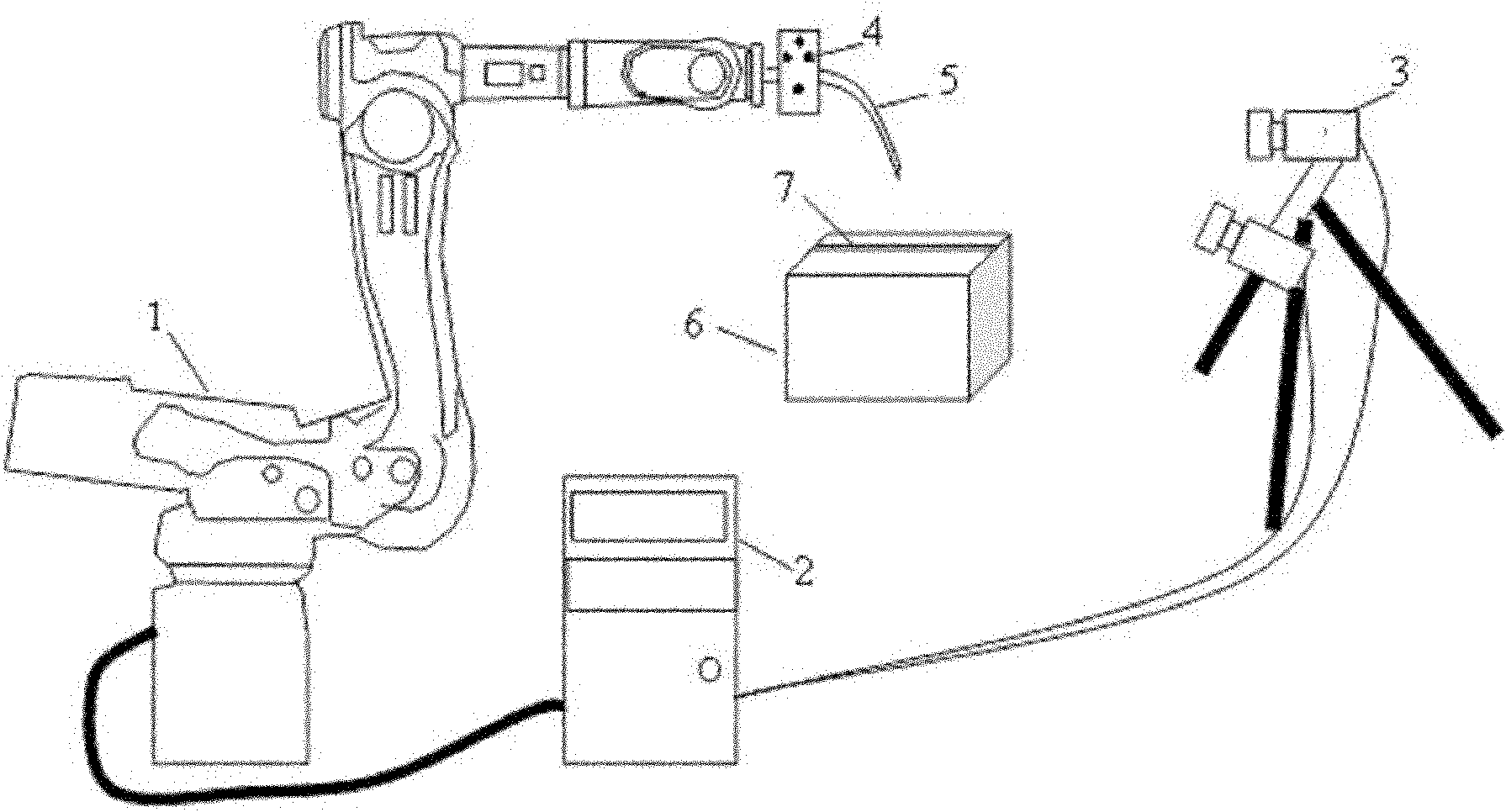
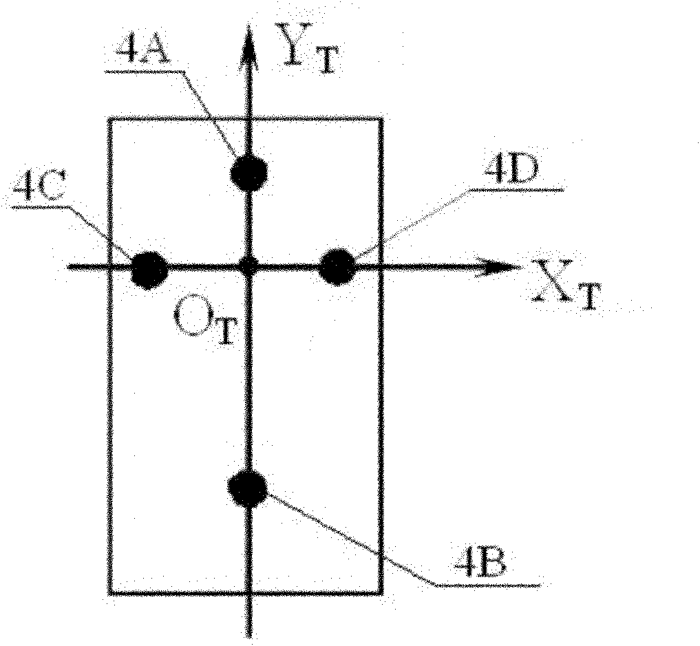
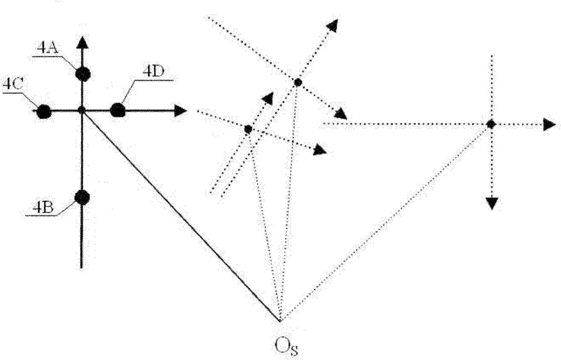
[0038] Figure 1 to Figure 6 It is the vision positioning based industrial robot control system and its control method described in Embodiment 1. The industrial robot control system such as figure 1 As shown, the system includes a robot 1, a robot controller 2 and a visual measuring device, the visual measuring device is a binocular visual measuring device 3, the robot 1 adopts a six-axis robot, and the end is provided with an operating tool 5, and the robot 1 passes the robot The controller 2 is connected with the binocular vision measuring device 3, and the robot controller 2 uses the positioning information of the binocular vision measuring device 3 as feedback information. The luminous marking point 4 is fixed on the operating tool 5 of the robot, and the binocular vision measuring device 3 measures the luminous marking point 4 in real time, and the movement trajectory of the robot end operation tool can be determined by measuring the luminous marking point. The binocula...

Embodiment 2

[0061] Such as Figure 7 As shown, the difference from Embodiment 1 is that five luminescent marking points are fixed on the operating tool, which are respectively the first marking point 4A, the second marking point 4B, the third marking point 4C, and the fourth marking point 4D. and fifth marking point 4E. The connecting line between the first marking point 4A and the second marking point 4B is perpendicular to the connecting line between the third marking point 4C and the fourth marking point 4D and intersects at a point, and the fifth marking point 4E is located at the intersection point. The more markers distributed, the less impact a single illuminated marker will have on motion accuracy.

[0062] Others are with embodiment 1.

Embodiment 3

[0064] Such as Figure 8 As shown, the difference from Embodiment 1 is that the operating tool is fixed with six luminous marking points, which are respectively the first marking point 4A, the second marking point 4B, the third marking point 4C, and the fourth marking point 4D. , the fifth marking point 4E and the sixth marking point 4F. Wherein the connecting line of the first marking point 4A, the second marking point 4B is perpendicular to the connecting line of the third marking point 4C and the fourth marking point 4D, and intersects at one point, the fifth marking point 4E is located on the intersection point, the sixth The marking point 4F is located directly below the second marking point 4B.


PUM


Abstract

The invention relates to the field of a robot, in particular to an industrial robot control system based on visual positioning and a control method thereof. The control system provided by the invention is convenient to operate and has the advantages of simple structure and high efficiency and accuracy. In artificial teaching process, positioning motion control process and oriented motion control process of the control method provided by the invention, the positioning of luminescence mark points or the ends of an operating tool is performed in the coordinates ow, xw, yw and zy of a visual measuring device, thus the control system has no requirement on the motion control accuracy of the robot and the relative position relation of the coordinates of the tool and the coordinates of the robot, and the control method only requires linear motion realized by the rotation of axes from the first axis to the third axis and rotary motion realized by the rotation of axes of axes from the fourth axis to the sixth axis according to the theoretical model of the robot and, thereby fundamentally avoiding the extremely strict requirements on the accuracy of a robot model and the calibrating accuracy of the coordinates of the tool in conventional off-line programming teaching and meeting the operating requirements of a complicated track with high accuracy.

Description

technical field [0001] The invention relates to the field of robots, in particular to a visual positioning-based industrial robot control system and a control method thereof. Background technique [0002] Industrial robots have been widely used in various industrial fields, such as robot welding, robot painting, robot handling, etc. In these fields, industrial robots replace humans to make repeatable and precise movements, thus ensuring the consistency of product quality. To complete a specific action, the robot must move along a specific trajectory. At present, there are two ways to plan the trajectory of the robot, one is online teaching, and the other is offline programming and teaching. [0003] Online teaching is to control the movement of the robot through the manual control box of the robot. The process of online teaching includes moving the end of the tools installed on the robot, such as spray guns and welding guns, to its operating position, and recording the coor...

Claims


Application Information

Patent Timeline
IPC IPC(8): G05D1/02
Inventor 解则晓于浩源王旭
Owner 解则晓
Why Eureka
Try Eureka