Landing rosin dissolution and separation device

A separation device, the technology of landing turpentine, applied in the direction of turpentine, natural resin refining, chemical instruments and methods, etc., can solve problems such as sticking to equipment, dissolution, affecting economic benefits, etc. Effect

Inactive Publication Date: 2011-08-03
古远亮
View PDF4 Cites 8 Cited by
  • Summary
  • Abstract
  • Description
  • Claims
  • Application Information

AI Technical Summary

Problems solved by technology

[0004] As the natural ground turpentine grows in contact with the air, the turpentine will continue to volatilize and become a yellow, brown or black solid. Because this turpentine is severely oxidized and contains high impurities, its physical and chemical properties are significantly different from fresh turpentine. Therefore, the current method is adopted. Conventional rosin production equipment cannot successfully separate active ingredients, let alone directly produce rosin products
Its characteristics are: in the heating and dissolving process, turpentine is usually added as a solvent to dissolve the turpentine, and the natural ground turpentine is severely oxidized, and the turpentine can no longer dissolve its oxides. After being heated, the oxidized turpentine becomes an extremely viscous black color. Jelly, this kind of jelly has a large specificity, settles at the bottom of the equipment, sticks to the equipment, and often blocks the pipeline, which can easily lead to safety accidents
Moreover, due to the high content of turpentine and bark impurities and sediment, a large amount of turpentine will be consumed when dissolving, which seriously affects economic benefits.

Method used


Image

  • Landing rosin dissolution and separation device
  • Landing rosin dissolution and separation device
  • Landing rosin dissolution and separation device

Examples


Embodiment Construction

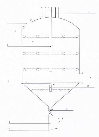
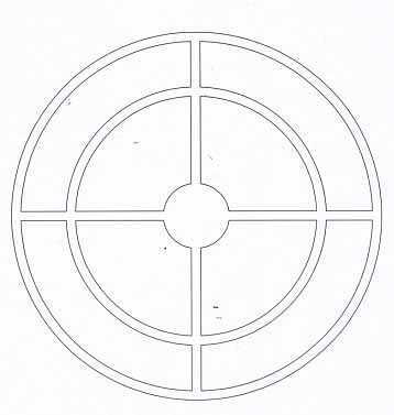
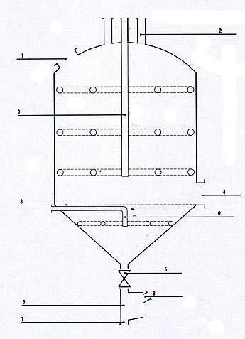
[0010] A floor-standing rosin melting and separating device, the device includes a cylindrical metal container with a conical bottom. Set a porous sieve plate 3, set a slag outlet 4 at the lower end of the cylinder and the upper edge of the sieve plate, set a gate valve 5 at the bottom of the funnel-shaped cone, set a turpentine and turpentine gas diversion tank 6 under the gate valve 5, and set a turpentine outlet 7 at the bottom of the tank , the top of the tank body is provided with a turpentine gas diversion inclined pipe 8, and the upper and lower steam injection systems 9 and 10 are established with the sieve plate in the container, and the steam pipes are arranged in a criss-cross pattern, and the opening angle of the injection holes is: limited by the level from 0 to negative 90 degrees. Its working process is: use steam to heat the ground rosin to make it melt under heat, and the melted rosin leaks to the bottom through the sieve plate and flows into the turpentine an...


PUM


Abstract

The invention discloses a landing rosin dissolution and separation device. The device comprises a metal container with a cylindrical cone bottom, the container is provided with an arched sealed top, the upper part of the container is provided with a feeding hole and an emptying pipe, a porous screen plate is arranged in the cut position of the cylinder and the cone bottom of the container, a slagdischarge hole is formed at the lower end of the cylinder and the upper edge of the screen plate, a gate valve is arranged at the lower part of the funnel-shaped cone bottom, a rosin and turpentine gas diversion tank is arranged below the gate valve, the lower part of the tank body is provided with a rosin outlet, the upper part of the tank body is provided with a turpentine gas diversion obliquepipe, upper and lower steam jet systems are arranged in the container by using the screen plate as the boundary, steam pipes are crossed vertically and horizontally, and the open angle of jet holes is from level limited 0 to negative 90 degrees. Through the device, rosin with little impurity is obtained, convenience is provided for further processing a rosin finished product, meanwhile, oil watervapor is condensed and transformed into turpentine, and the turpentine serving as a solvent does not need to be added; and the device is simple and convenience for operation, and has one-step effect.

Description

technical field [0001] The invention relates to a technique for obtaining turpentine and turpentine by melting and separating ground pine resin, in particular to a ground pine resin melting and separating device. Background technique [0002] Pine trees are subject to pest damage and other trauma, and the wound will flow out a lot of turpentine, which accumulates over time and gathers in the roots of pine trees. Usually, this pine resin is called ground pine resin. The present invention collects this ground pine resin and separates effective ingredients. [0003] Pine resin is a mixture of rosin and turpentine, and it is a colorless and transparent viscous liquid when it first flows out from the tree body. At present, it is obtained by artificially collecting turpentine, and then processed into rosin and turpentine, which become important chemical raw materials. There are two kinds of processing methods for artificially collected rosin: steam method and drip method. The s...

Claims


Application Information

Patent Timeline
Patent Type & Authority Applications(China)
IPC IPC(8): C09F3/00C09F1/02
Inventor 古远亮
Owner 古远亮
Why Eureka
Try Eureka