Method and device for reinforcing bridge by external pre-stressed strands under bridge

A technology of prestressed steel strands and external prestressing, applied in bridge reinforcement, bridges, bridge maintenance, etc., can solve the problems of hidden accidents, difficult construction, self-heavy and other problems, and achieve simple reinforcement structure, low reinforcement cost and high effect obvious effect

Inactive Publication Date: 2011-08-03
ZHEJIANG ELECTRIC POWER DESIGN INST
View PDF5 Cites 16 Cited by
  • Summary
  • Abstract
  • Description
  • Claims
  • Application Information

AI Technical Summary

Problems solved by technology

[0003] At present, the reinforcement methods for long-span bridges are as follows: one is to use carbon fiber or aromatic glass tough cloth to strengthen the bridge technology, which requires high leveling construction and is difficult to destroy the road surface construction; the other is to use steel column support to strengthen the bridge method, which is Cast-in-situ piles are laid on the outside of the river bridge deck to construct the bridge abutment, but when the bridge deck is wide and the net height under the bridge is small, the middle part cannot enter the piling machine, so the construction is difficult; the third is to use shipboard support to strengthen the bridge method, this method The obtained reinforced bearing capacity is easily affected by the fluctuation of the river water, especially when the river water is soaring, there is a greater hidden danger of accidents; the fourth is to use a temporary method of strengthening the bridge with a steel frame bridge on the bridge, which is suitable for 8-12m small and medium-sized bridges. For span bridges, the abutments on both sides of the bridge have no obvious defects. When the span is large, the abutments will not be able to bear the pressure due to their own weight

Method used


Image

  • Method and device for reinforcing bridge by external pre-stressed strands under bridge
  • Method and device for reinforcing bridge by external pre-stressed strands under bridge
  • Method and device for reinforcing bridge by external pre-stressed strands under bridge

Examples


Embodiment Construction

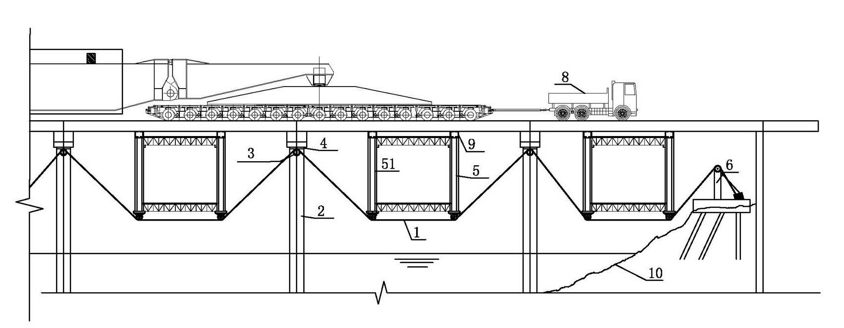
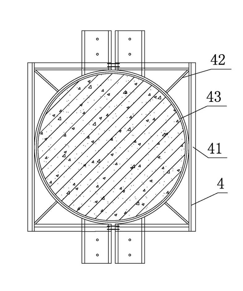
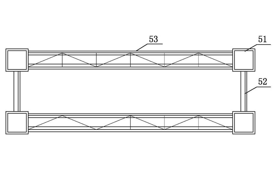
[0015] The present invention will be described in detail below in conjunction with the accompanying drawings: the method for externally prestressed reinforced bridge under the bridge of the present invention, the method is: first install the steel hoop for fixing the prestressed steel strand on the top of the bridge pier , the steel hoop is lined with rubber sheets, and a small steel frame that can be tightly supported under the bridge deck is temporarily supported under the bridge deck between the two piers, and the prestressed steel strand is fixed on the steel hoop through a pulley, and then Fix it on the above-mentioned small steel frame, and finally fix the two ends of the prestressed steel strand on the tension support column and the support on the ground, and adjust the tension force of the prestressed steel strand to generate prestress Stretching, so that the small steel frame generates an upward lifting force on the bridge deck beam slab after being stressed.

[0016]...


PUM


Abstract

The invention provides a method and device for reinforcing a bridge by external pre-stressed strands under the bridge. The method comprises the following steps: firstly installing steel hoops for fixing the pre-stressed strands at the upper parts of bridge piers; temporarily arranging small steel frames for firmly supporting the lower part of the bridge surface between two bridge piers; fixing the pre-stressed strands on the steel hoops through special pulleys, then fixing the strands on the small steel frames, and finally fixing two ends of the pre-stressed strands on tension support pillars and bearings on the ground; and adjusting tensioning force of the pre-stressed strands so as to generate pre-stress stretching, so that the small steel frames generate upward lifting force for the lower part of the bridge surface under stress. The invention has the characteristics that as the components such as the steel hoops, the small steel frames, the support pillars, the bearings and the like can be dismantled, carried back and reused (equivalent to rental), reinforcement cost of the bridge is low; increment of pressure and shear force on the bridge piers caused by the upward lifting force generated by pre-stress is zero, thus not causing any damage on structures of the original bridge such as the bridge surface and the like; and construction process is convenient, the reinforced structure is simple and practical, and reinforcement effect is obvious.

Description

technical field [0001] The invention relates to a reinforcement method and a device for a large multi-span bridge, belonging to a bridge reinforcement method and a reinforcement device. Background technique [0002] At present, large-scale equipment such as UHV substations or DC converter stations has a heavy load, and the transportation weight is 340-390T. Due to the limitation of width and height of railway transportation, it cannot be transported. Generally, the large-scale equipment transportation scheme of water transportation and road is adopted. That is, the main transformer is first transported along the channel to the large wharf closest to the station site, and then transported to the station site by road on a flatbed truck. Among them, the road transportation will pass through some bridges with large spans, and these bridges cannot carry large-scale equipment due to the bearing capacity. To meet the transportation of large-scale equipment, the long-span bridges ne...

Claims


Application Information

Patent Timeline
IPC IPC(8): E01D22/00
Inventor 黄达余安春秀梅狄克邵雪军吴亮盛晓红
Owner ZHEJIANG ELECTRIC POWER DESIGN INST
Why Eureka
Try Eureka