
Method for electrical detection on wire harnesses of different sizes and universal test fixture

A technology for electrical testing and general testing, applied to parts of electrical measuring instruments, measuring electricity, measuring devices, etc., can solve the problems of increasing the number of testing jig management personnel and management difficulty, occupying storage space, and eliminating the need for production costs, etc. To achieve the effect of simple and rapid detection process, improve efficiency and reduce production costs

Inactive Publication Date: 2011-08-03
东莞市锐升电线电缆有限公司
View PDF5 Cites 12 Cited by
  • Summary
  • Abstract
  • Description
  • Claims
  • Application Information

AI Technical Summary

Problems solved by technology

However, as the number of wire harness products produced by the enterprise increases, more and more testing fixtures are required, which leads to various adverse and negative effects. For example, a large amount of materials are used in the manufacture of testing fixtures. After the production of the corresponding wiring harness was stopped, the inspection fixture was discarded, which led to the waste of raw materials; a large number of inspection fixtures occupied the limited storage space of the enterprise; increased the number of management personnel and the difficulty of management of the inspection fixture
As a result, the company has paid a lot of unnecessary production costs for the inspection fixture

Method used


Image

  • Method for electrical detection on wire harnesses of different sizes and universal test fixture
  • Method for electrical detection on wire harnesses of different sizes and universal test fixture

Examples


Embodiment

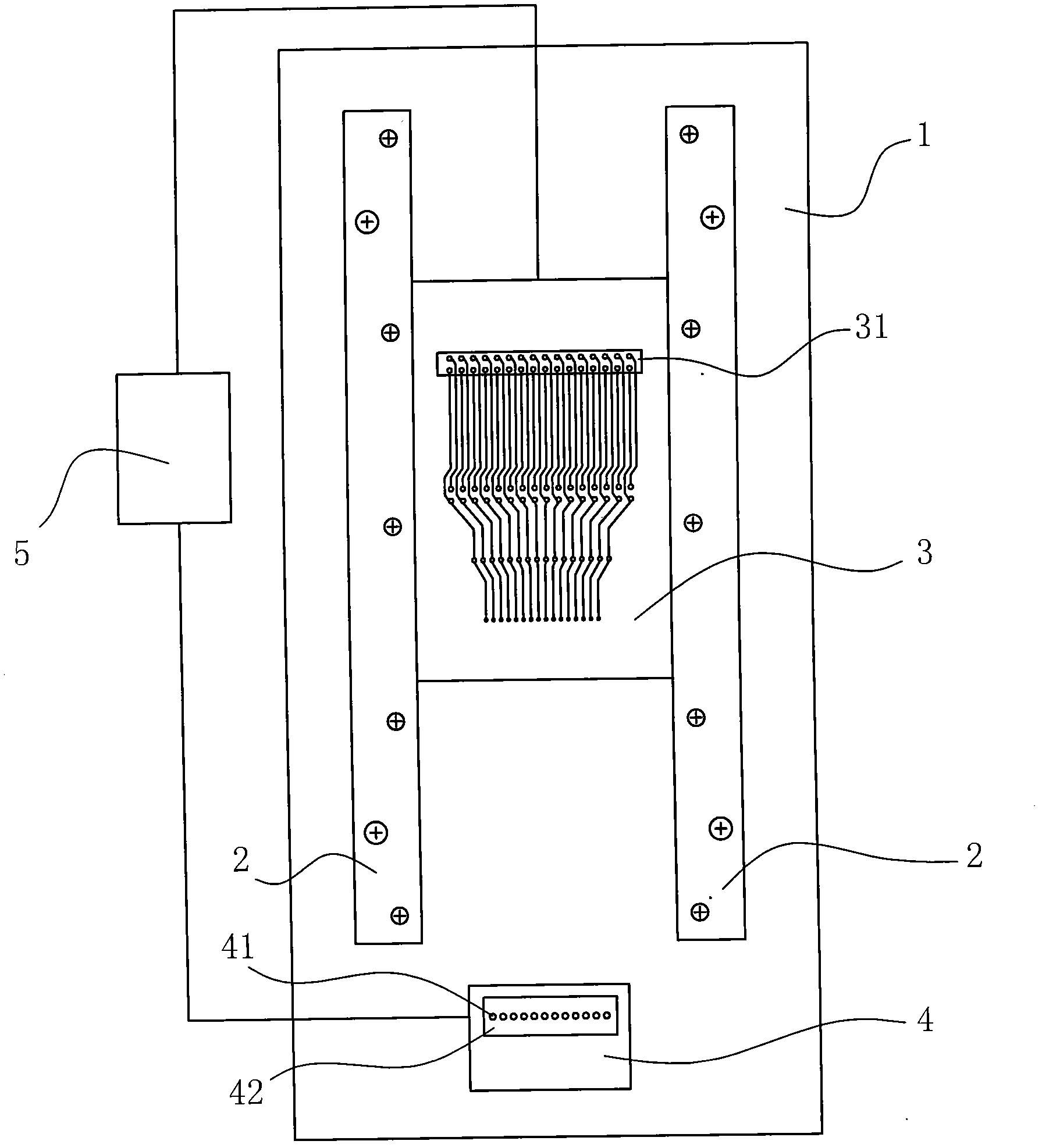
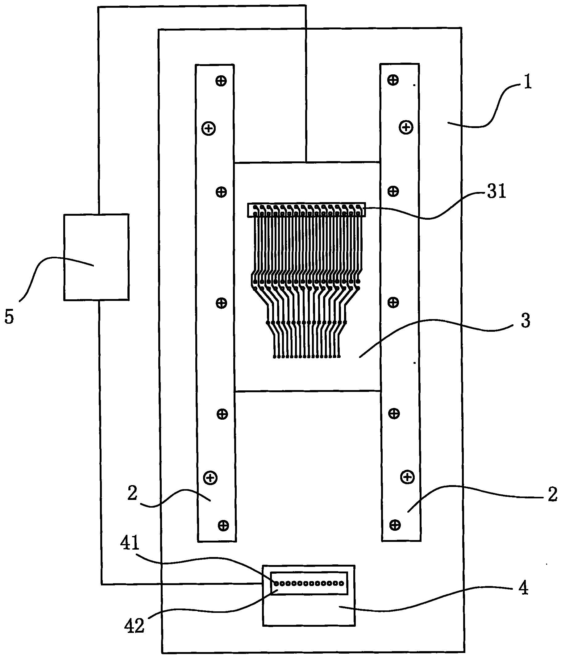
[0022] Example: see figure 1 , a method for electrical detection of wire harnesses of different specifications of the present invention, which comprises the following steps:

[0023] (1) Two slide rails 2 are arranged side by side on an installation and operation platform 1;

[0024] (2) Prepare a plurality of detection circuit boards 3, the size of the detection circuit boards 3 is the same, and a butt connector 31 is integrated on a detection circuit board 3 corresponding to the connector specification at one end of the wiring harness to be detected;

[0025] (3) Prepare an error-proof test device 4, and integrate a row of pins 41 in the error-proof test device 4. The pins 41 correspond to the jack-type connectors at the other end of the wire harnesses of different specifications, and can be used with a variety of different specifications. Jack connector docking;

[0026] (4) Select a corresponding detection circuit board 3 according to the wire harness connector specifica...


PUM


Abstract

The invention discloses a method for electrical detection on wire harnesses of different sizes, which comprises the following steps of: parallelly arranging two sliding rails on an installation operating platform; preparing a plurality of detection circuit boards, wherein a butting connector is integrated on a detection circuit board correspondingly according to the size of a connector arranged at one end part of a wire harness to be detected; preparing an error-proof test device, wherein a row of pins are integrated in the error-proof test device and the pins correspond to jack connectors atthe other ends of the different-size wire harnesses; selecting a corresponding detection circuit board according to the size of the connector of the wire harness to be detected; respectively and electrically connecting the error-proof test device and the detection circuit boards with a test machine; butting the jack connectors arranged at one end of the wire harness to be detected with the pins on the error-proof test device; and butting the connectors arranged at the other end of the wire harness to be detected with the butting connectors on the circuit boards. By the method, electrical detection on the wire harness can be performed by the testing machine, and corresponding detection circuit board is only required to be changed if another size of wire harness is detected.

Description

technical field [0001] The invention belongs to testing equipment, in particular to a method for electrical testing of wire harnesses of different specifications and a general testing fixture for implementing the method. Background technique [0002] In the prior art, the wiring harness is an electronic component with a wide range of uses. Most electronic products need to be operated through electrical control. The wiring harness must be used to connect the various components. The failure of the wiring harness will directly affect the use of the wiring harness. The overall quality of the product can easily lead to accidents. In the manufacturing process of the wire harness, it is necessary to check whether the electrical performance of the normally manufactured wire harness is qualified, and whether the contact resistance, insulation resistance and electric strength meet the set requirements for use. In the prior art, a jig is used for electrical testing of the wire harness...

Claims


Application Information

Patent Timeline
IPC IPC(8): G01R31/00G01R31/02G01R1/02
Inventor 匡俊英
Owner 东莞市锐升电线电缆有限公司
Learn More