Auxiliary detection device and method for ultraviolet laser interference fringe

An ultraviolet laser and auxiliary detection technology, which is applied in the exposure device, optics, and optical components of the photographic plate-making process. The effect of shortening the cycle

Inactive Publication Date: 2011-08-03
INST OF SEMICONDUCTORS - CHINESE ACAD OF SCI
View PDF5 Cites 11 Cited by
  • Summary
  • Abstract
  • Description
  • Claims
  • Application Information

AI Technical Summary

Problems solved by technology

Disadvantages: The detection area and the lithography substrate area are not in the same position, and the detection fringes cannot fully reflect the actual fringe characteristics on the lithography substrate. At the same time, the detection area is inconsistent with the actual lithography surface, and the uniformity of the fringes cannot be monitored; it affects the stability of the optical path The accuracy of observation is limited by the resolution of the photosensitive substrate
Disadva

Method used


Image

  • Auxiliary detection device and method for ultraviolet laser interference fringe
  • Auxiliary detection device and method for ultraviolet laser interference fringe
  • Auxiliary detection device and method for ultraviolet laser interference fringe

Examples


Example Embodiment

[0025] In order to make the objectives, technical solutions and advantages of the present invention clearer, the present invention will be further described in detail below with reference to specific embodiments and accompanying drawings.

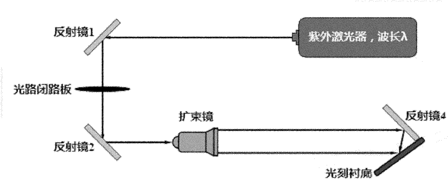
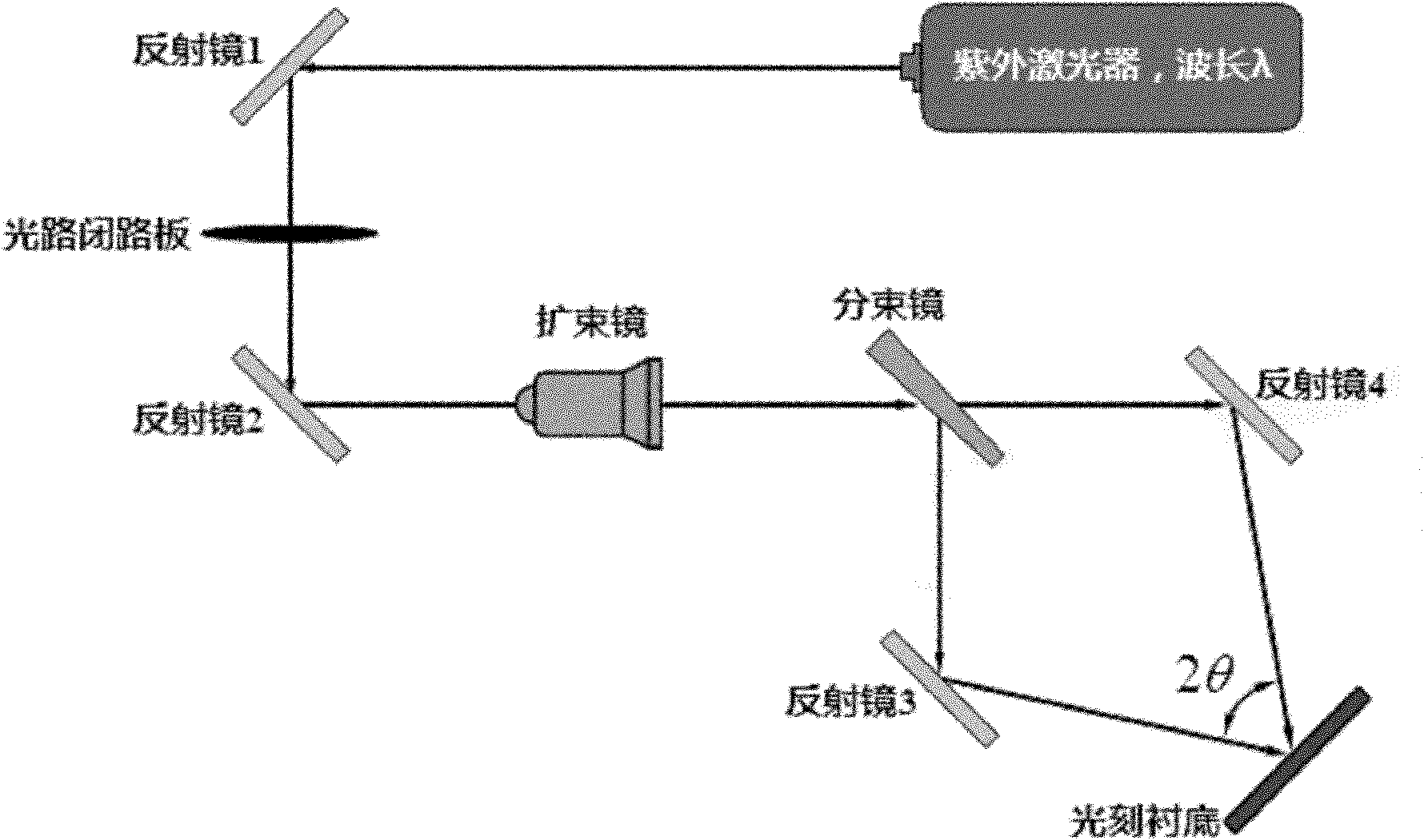
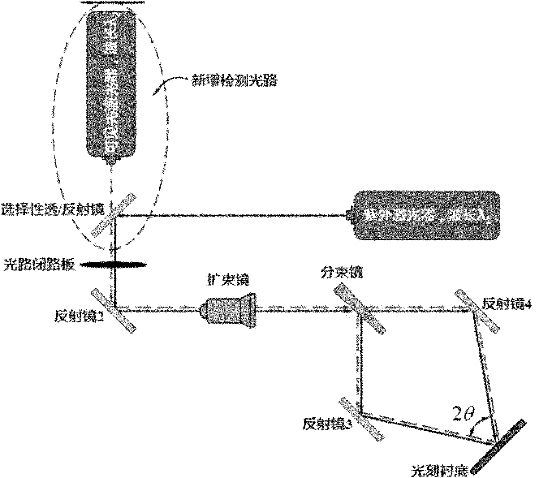
[0026] In an exemplary embodiment of the present invention, an auxiliary detection device for ultraviolet laser interference fringes is applied in an ultraviolet laser holographic lithography system, including: a visible light laser and an auxiliary detection optical path. The visible light laser is used to generate an auxiliary detection laser in the visible light band, and the wavelength of the auxiliary detection laser satisfies a preset relationship with the wavelength of the ultraviolet laser; the auxiliary detection optical path is used for the auxiliary detection laser in the ultraviolet laser holographic lithography system. Through the passage, the two sub-optical paths of the auxiliary detection optical path are respectively paralle...


PUM

PropertyMeasurementUnit
Wavelengthaaaaaaaaaa

Abstract

The invention discloses an auxiliary detection device and a method for an ultraviolet laser interference fringe. In the auxiliary detection device, a visible laser light path is additionally arranged in an ultraviolet laser holographic lithography system; and after the relation between visible laser wavelength and ultraviolet laser wavelength is determined, the period of the ultraviolet laser interference fringe is detected through observing a visible laser interference fringe, therefore, the process of detecting the ultraviolet laser interference fringe in the ultraviolet laser holographic lithography system is simplified, the period of the holographic lithography process is shortened, and the cost of the lithography process is reduced.

Description

technical field [0001] The invention relates to the technical field of microelectronics in the optical industry, in particular to an auxiliary detection device and method for ultraviolet laser interference fringes. Background technique [0002] In order to realize single-frequency operation of semiconductor laser diodes, distributed feedback (DFB for short) and distribution Bragg reflection (DBR for short) structures are usually used for mode selection of the lasing wavelength. Such DFB and DBR structures are actually a series of large-scale, repetitive grating structures of specific periods. [0003] Since the wavelength of semiconductor lasers is usually in the range of 1600nm to 400nm, the grating period for wavelength mode selection is in the order of hundreds of nanometers, and some are even smaller than 200nm. The grating structure on this semiconductor laser is realized by photolithography and etching technology. Due to the large production area and good repeatabili...

Claims


Application Information

Patent Timeline
IPC IPC(8): G03F7/20G02B27/10
Inventor 郑凯赵懿昊李全宁熊聪
Owner INST OF SEMICONDUCTORS - CHINESE ACAD OF SCI
Why Eureka
Try Eureka