
Arc blade milling machine for swing arm tool

A technology of circular arc edge and swing arm type, which is applied to the lathe tool, planer/slotting machine tool, planer, etc. It can solve the problems of large friction coefficient, large resilience and high cost of the sliding table. Achieve the effects of improving efficiency and precision, guaranteeing cutting accuracy, and small friction

Inactive Publication Date: 2011-08-10
丁珍华
View PDF8 Cites 15 Cited by
  • Summary
  • Abstract
  • Description
  • Claims
  • Application Information

AI Technical Summary

Problems solved by technology

In the superhard sharpening machines currently on the market, the feed mechanism is heavy due to the weight of the slide table, and the friction coefficient of the slide table is relatively large, so the rebound force is relatively large when the tool is sharpened, so it is difficult to grind brittle materials such as single crystal diamond. For large knives, the cutting edge is easy to crack; some scholars have proposed to use magnetic or air-suspended sliding table mechanism, but its cost is high, so it is rarely used in the market. In addition, the superhard tool sharpening equipment currently on the market has a complex structure and high cost

Method used


Image

  • Arc blade milling machine for swing arm tool
  • Arc blade milling machine for swing arm tool
  • Arc blade milling machine for swing arm tool

Examples


Embodiment 1

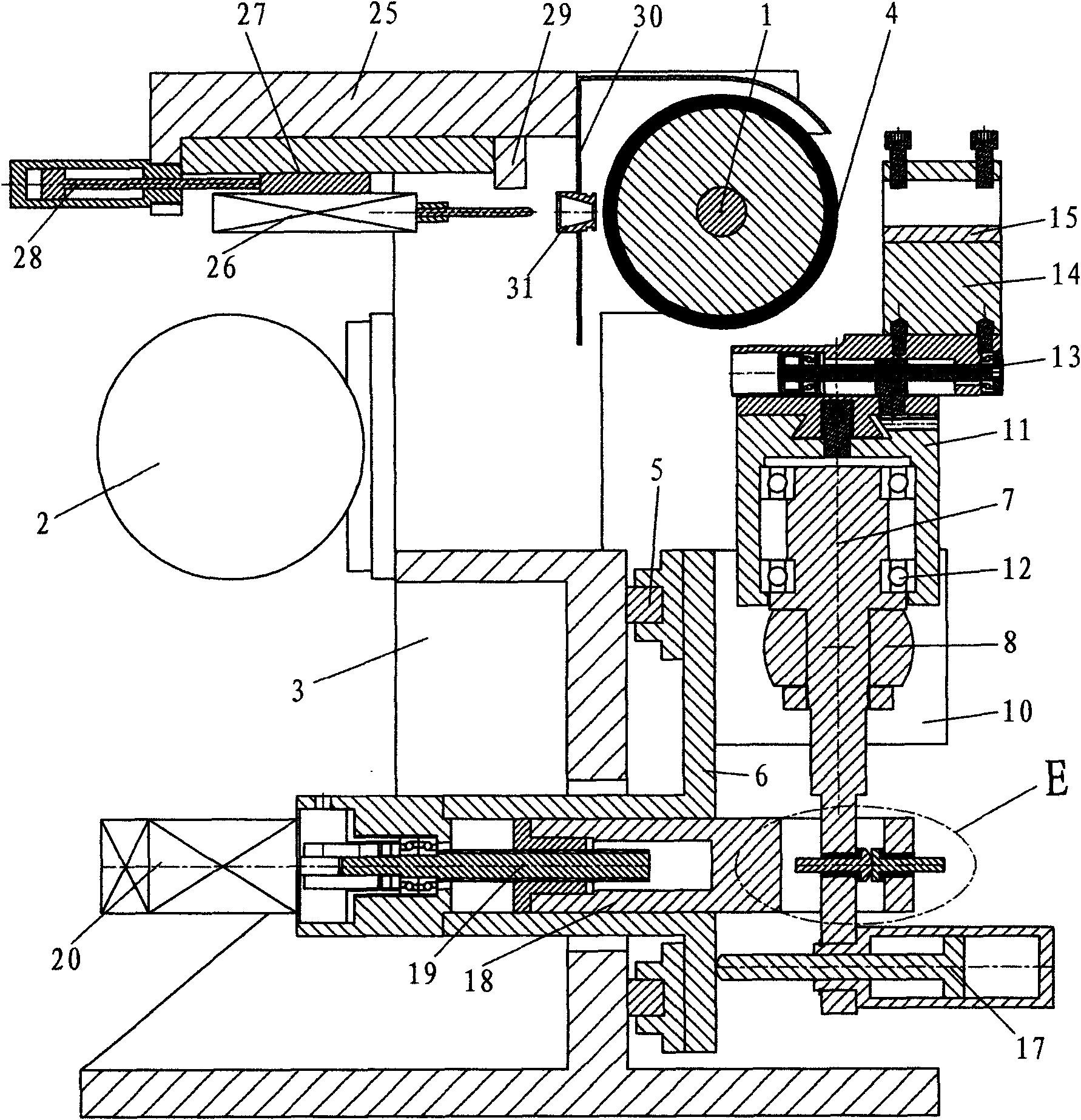
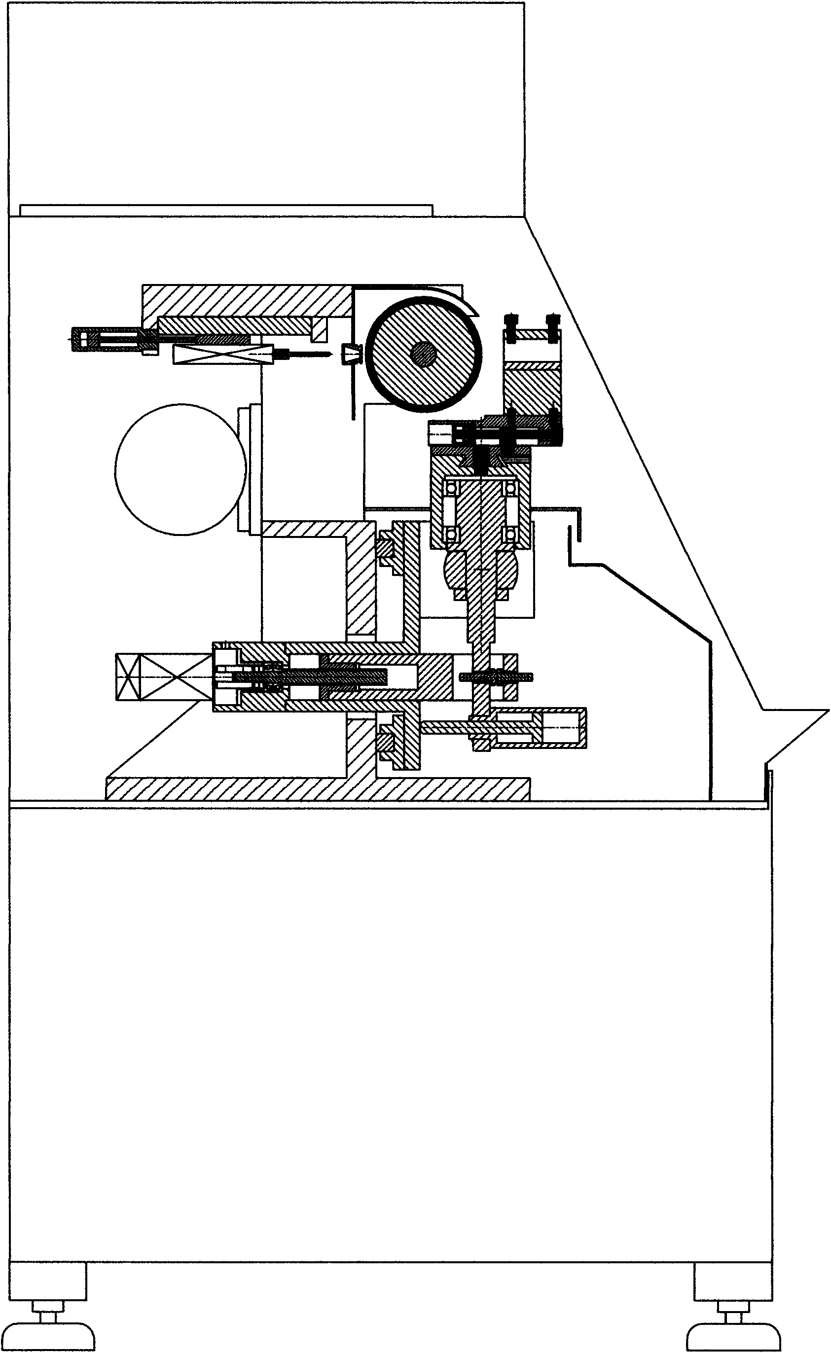
[0021] refer to figure 1 As shown, the grinding head assembly (1) and the motor (2) of this embodiment are fixedly installed on the body (3) together, and the grinding wheel surface (4) is installed in parallel with the grinding head assembly (1). A longitudinal slide table (6) is installed on the body (3) with two rolling guide rails (5) parallel to the grinding head assembly (1). refer to figure 1 , 4As shown, the swing arm in this embodiment is composed of a swing arm (7), a central shaft (8), a bearing (9), and a bearing seat (10). fit into a cross shaft frame; a pair of bearings (9) at both ends of the central shaft (8) are fixedly installed on the longitudinal sliding table (6) through the bearing seat (10), and the central point of the central shaft (8) is at the horizontal 1 mm from the grinding wheel surface in the direction. The upper end of the swing arm (7) is processed into a shaft shape, which is directly used as the mandrel of the rotary table (11), and the ...

Embodiment 2

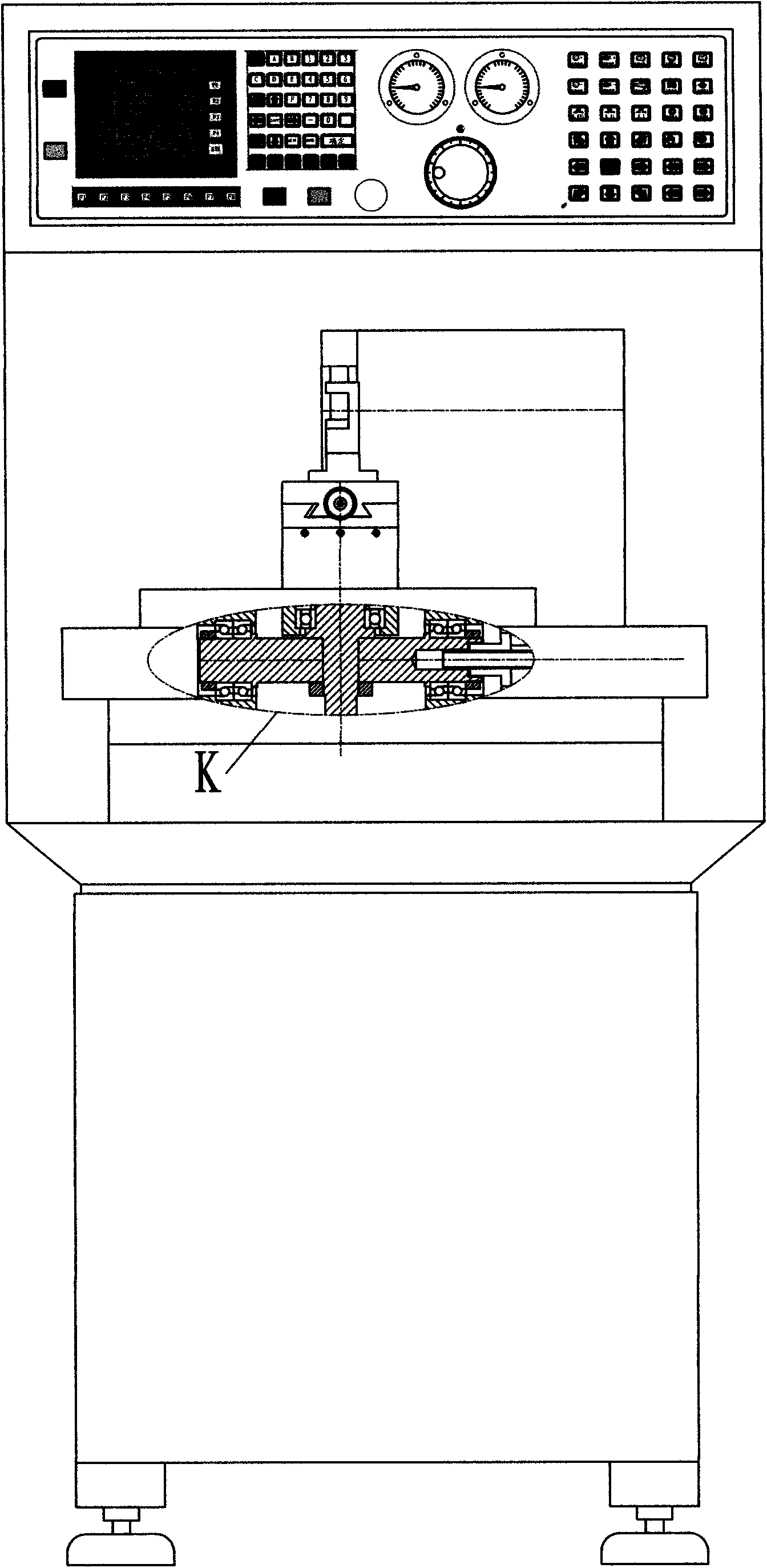
[0026] refer to Figure 6 , 7 As shown, the present embodiment grinding head assembly 2 (36) and motor 2 (37) are fixedly installed on the body 2 (38), and the emery wheel surface 2 (39) is parallel to the grinding head assembly 2 (36). In this embodiment, the swing arm is directly composed of cross shafts, and the two ends of the swing arm transverse axis (40) are mounted on the body 2 (38) with clearance fit, and the center point of the swing arm transverse axis (40) is horizontal. 2 (39) 1 mm from the grinding wheel face in the direction. The upper end of the vertical shaft of the swing arm (41) is assembled into a flexible rotary table 2 (43) through the bearing 3 (42) and the rotary table; a small cross slide table 2 (44) is installed on the rotary table 2 (43). ), a knife rest 2 (45) is installed on the small cross slide table 2 (44), and a module knife shim 2 (46) is placed in the knife rest 2 (45). In order to improve the precision of the rotary table 2 (43), the ro...


PUM


Abstract

The invention discloses an arc blade milling machine for a swing arm tool, which mainly comprises a machine body, a control system, a milling head assembly, a small cross-shaped slide seat, a revolving working platform and a tool rest. The arc blade milling machine is characterized in that a feed moving mechanism adopts a swing arm mechanism; the revolving working platform is installed on a swing arm and is provided with the small cross-shaped slide seat, and the small cross-shaped slide seat is provided with the tool rest; the machine body is provided with a reciprocation sliding table parallel to a milling wheel surface direction; and the milling head assembly or the swing arm mechanism is installed on the reciprocation sliding table. The arc blade milling machine for the swing arm tool has the advantages of good feed flexibility, simple and economic structure, strong principal axis rigidity and good blade milling quality, and is widely suitable for milling precise machining tools and super hard tools.

Description

technical field [0001] The invention relates to a cutting tool sharpening machine, in particular to an arc sharpening machine for superhard cutting tools. technical background [0002] With the popularization and application of cutting tools made of superhard materials such as diamond, cubic boron nitride, and ceramics, especially the new trend of turning grinding instead of grinding, people have become more and more demanding on the sharpening of turning tools. Traditional manual grinding of turning tools It has been difficult to meet the requirements, especially in terms of finish, which has prompted people to pay more and more attention to machine grinding tools. In the superhard sharpening machines currently on the market, the feed mechanism is heavy due to the weight of the slide table, and the friction coefficient of the slide table is relatively large, so the rebound force is relatively large when the tool is sharpened, so it is difficult to grind brittle materials su...

Claims


Application Information

Patent Timeline
IPC IPC(8): B24B3/34
Inventor 丁珍华
Owner 丁珍华
Learn More