
Knitting machine

A knitting machine and warp knitting technology, applied in the field of knitting machines, can solve the problems of reduced productivity, fast running speed, cloth waste, etc., and achieve the effect of increasing winding space, increasing coiling length, and reducing labor intensity

Inactive Publication Date: 2011-08-10
NINGBO SANDO KNITTING
View PDF9 Cites 3 Cited by
  • Summary
  • Abstract
  • Description
  • Claims
  • Application Information

AI Technical Summary

Problems solved by technology

[0002] The weaving machine is a device used to weave yarn into cloth, but when processing elastic fabrics, due to the elasticity of the cloth, the two sides of the cloth will shrink towards the middle during the process of rolling the cloth into a roll, resulting in two The tension on the side cloth edges is relatively loose, which is easy to cause end cracks on the edge warp of the two cloth edges, and the running speed of the equipment is very fast. Once the edge warp breaks, a long section of cloth will become waste, which affects the quality of the product. Quality and efficiency; in addition, the current weaving machine has a limited length of each roll of cloth, and each roll of cloth can only be controlled within the range of 500 meters, and after a roll of cloth is taken up, it needs to be stopped first and then unloaded, resulting in the shutdown of the equipment The production rate is relatively high, and the number of times the operator lowers the cloth is relatively frequent, which increases the labor intensity of the employees and reduces the productivity

Method used

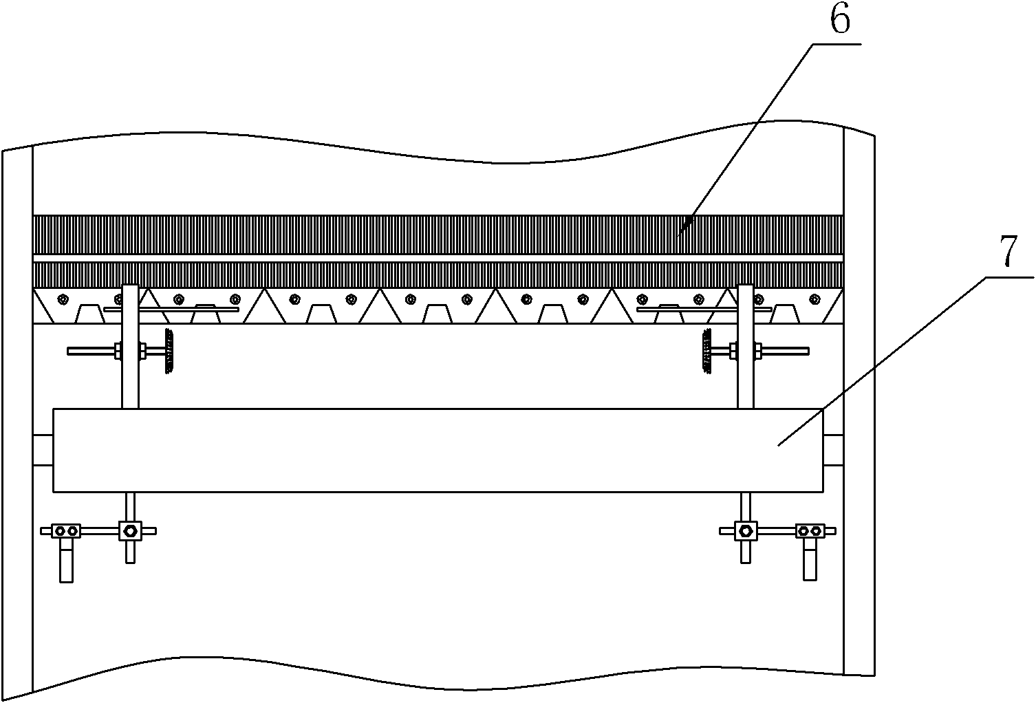
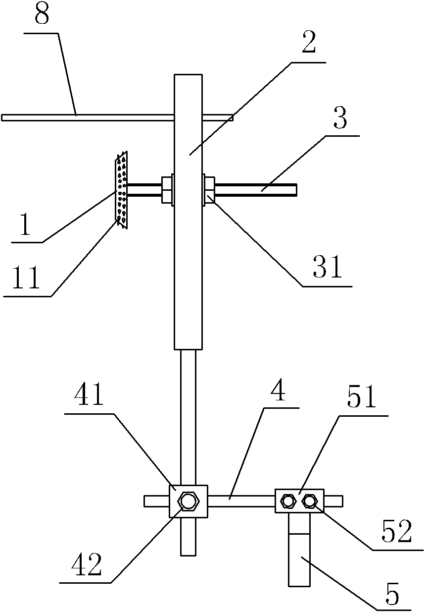
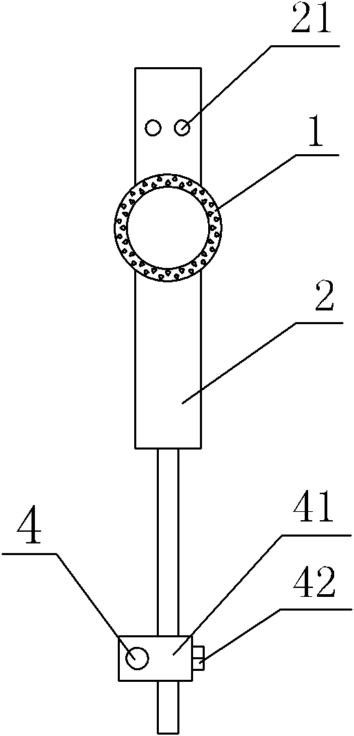

Image

  • Knitting machine
  • Knitting machine
  • Knitting machine

Examples


Embodiment Construction

[0021] The present invention will be further described in detail below in conjunction with the accompanying drawings and embodiments.

[0022] As shown in the figure, a knitting machine includes a warp knitting assembly 6, a first traction shaft 7, a cloth take-up device, a cloth tension adjustment device and an edge warp breaking self-stopping device, and the cloth tension adjustment device includes a truncated conical pressure wheel 1 , fixed rod 2, support rod 5, the first connecting rod 3, the second connecting rod 4 and the pick bar 8, the pinch roller 1 is positioned between the warp knitting assembly 6 and the first traction shaft 7, the outer circumference of the pinch roller 1 A plurality of evenly distributed protruding points 11 are integrally provided, the pressure wheel 1 is axially connected to the first connecting rod 3, the first connecting rod 3 is a screw rod, the first connecting rod 3 is screw connected to the fixed rod 2, and the first connecting rod 3 is ...


PUM


Abstract

The invention discloses a knitting machine, which comprises a warp knitting assembly, a first traction shaft and a cloth coiling device. The knitting machine is characterized in that the knitting machine comprises a cloth tension adjusting device, wherein the cloth tension adjusting device comprises a pinch roller, a fixed rod and a first connecting rod; the pinch roller is positioned between the warp knitting assembly and the first traction shaft; the pinch roller is coupled on the first connecting rod; the first connecting rod is connected on the fixed rod; the fixed rod is connected on the knitting machine; and a plurality of uniformly distributed spurs are integrally arranged on the peripheral surface of the pinch roller. The knitting machine has the advantages that: when the knitting machine processes elastic cloth, two sides of the cloth are pressed by using the pinch roller in a process of coiling the elastic cloth into a cloth coil, so that the two sides of the cloth are prevented from being contracted to the middle, the two sides of the cloth are tensioned, and loss of the cloth is prevented due to edge breakage of the cloth; and a vertical displacement adjusting mechanism is arranged on the fixed rod, and a horizontal displacement adjusting mechanism is arranged on a second connecting rod, so that the requirements for processing the cloth of different widths and different fabrics are met by adjusting the positions of the pinch roller in the horizontal and vertical directions.

Description

technical field [0001] The present invention relates to a knitting machine. Background technique [0002] The weaving machine is a device used to weave yarn into cloth, but when processing elastic fabrics, due to the elasticity of the cloth, the two sides of the cloth will shrink towards the middle during the process of rolling the cloth into a roll, resulting in two The tension on the side cloth edges is relatively loose, which is easy to cause end cracks on the edge warp of the two cloth edges, and the running speed of the equipment is very fast. Once the edge warp breaks, a long section of cloth will become waste, which affects the quality of the product. Quality and efficiency; in addition, the current weaving machine has a limited length of each roll of cloth, and each roll of cloth can only be controlled within the range of 500 meters, and after a roll of cloth is taken up, it needs to be stopped first and then unloaded, resulting in the shutdown of the equipment The ...

Claims


Application Information

Patent Timeline
Patent Type & Authority Applications(China)
IPC IPC(8): D04B27/36D04B35/14
Inventor 吴剑明夏俊杰
Owner NINGBO SANDO KNITTING
Learn More