Radiating fin of magnetron

A heat sink and magnetron technology, which is applied in the field of magnetron, can solve the problems that the heat sink blades reduce the air circulation space of the heat sink, the overall heat dissipation capacity of the heat sink cannot reach, and the motherboard increases the thickness of the heat sink blades, etc., so as to reduce the temperature, Improved heat conduction efficiency and improved performance

Inactive Publication Date: 2011-08-10
LG ELECTRONICS (TIANJIN) APPLIANCES CO LTD
View PDF0 Cites 4 Cited by
  • Summary
  • Abstract
  • Description
  • Claims
  • Application Information

AI Technical Summary

Problems solved by technology

When the magnetron is in use, a large amount of heat generated by the anode exchanges heat with the flowing air through the heat sink group. The key to the heat dissipation on the anode lies in the thickness of the main board of the heat sink in contact with the anode. The greater the thickness of the main board, the greater the heat dissipation capacity. The stronger it is, but the thickness of each part of the heat sink in the prior art is the same, increasing the thickness of the main board also increases the thickness of the heat dissipation blades, thereby increasing the overall cost of the heat sink, and because the thickness of the heat dissipation blades increases. Correspondingly, the air circulation space between the heat sinks is reduced, and the resistance to air flow is increased, so that the overall heat dissipation capacity of the heat sink cannot meet the design expectations.

Method used


Image

  • Radiating fin of magnetron
  • Radiating fin of magnetron
  • Radiating fin of magnetron

Examples


Embodiment Construction

[0026] The present invention will be described in detail below in conjunction with the accompanying drawings and embodiments.

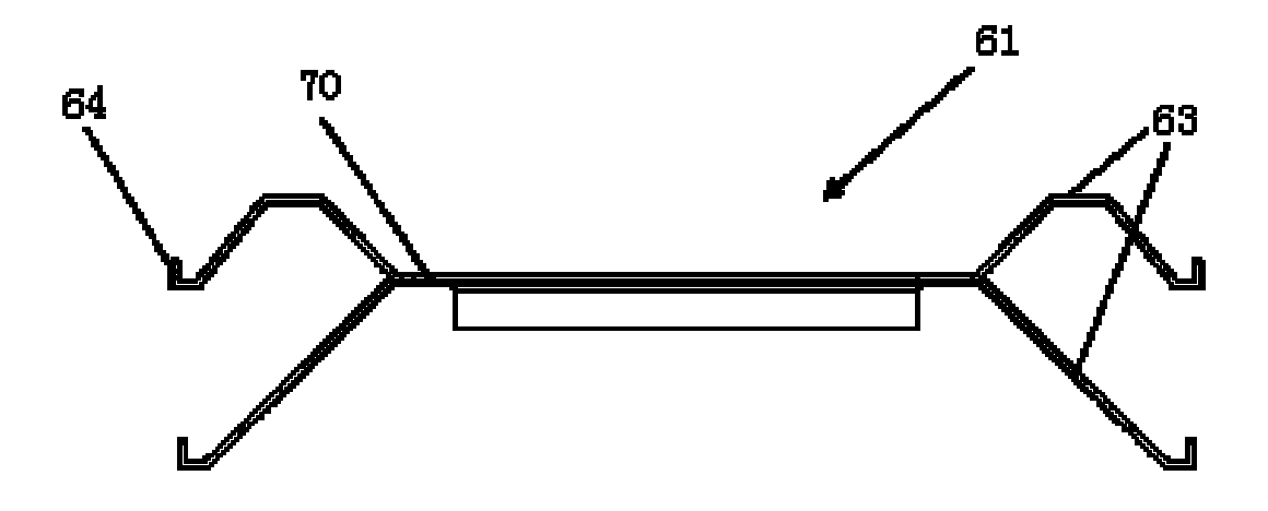
[0027] Figure 4 It is a side view of the heat sink of the magnetron of the present invention.

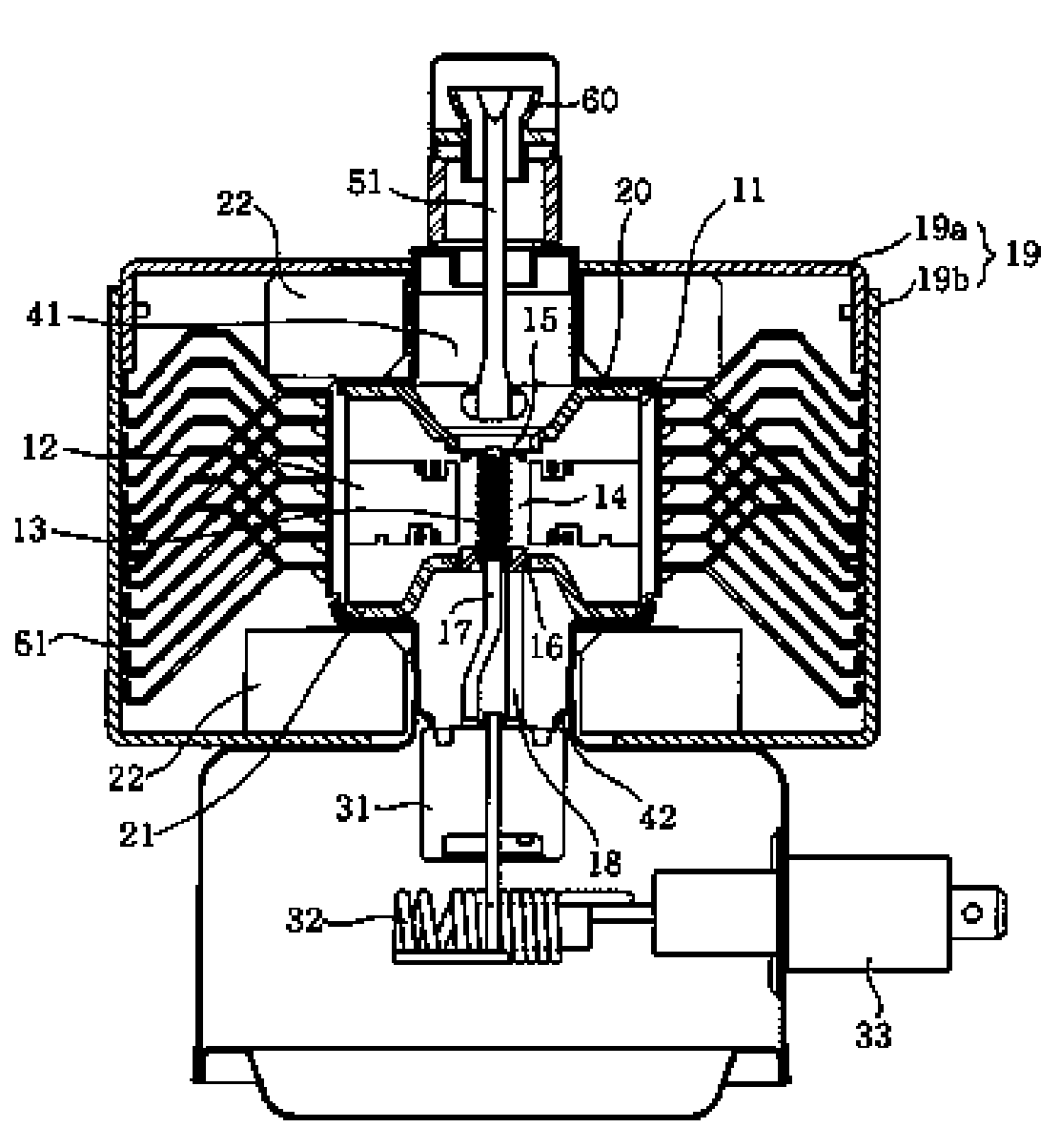
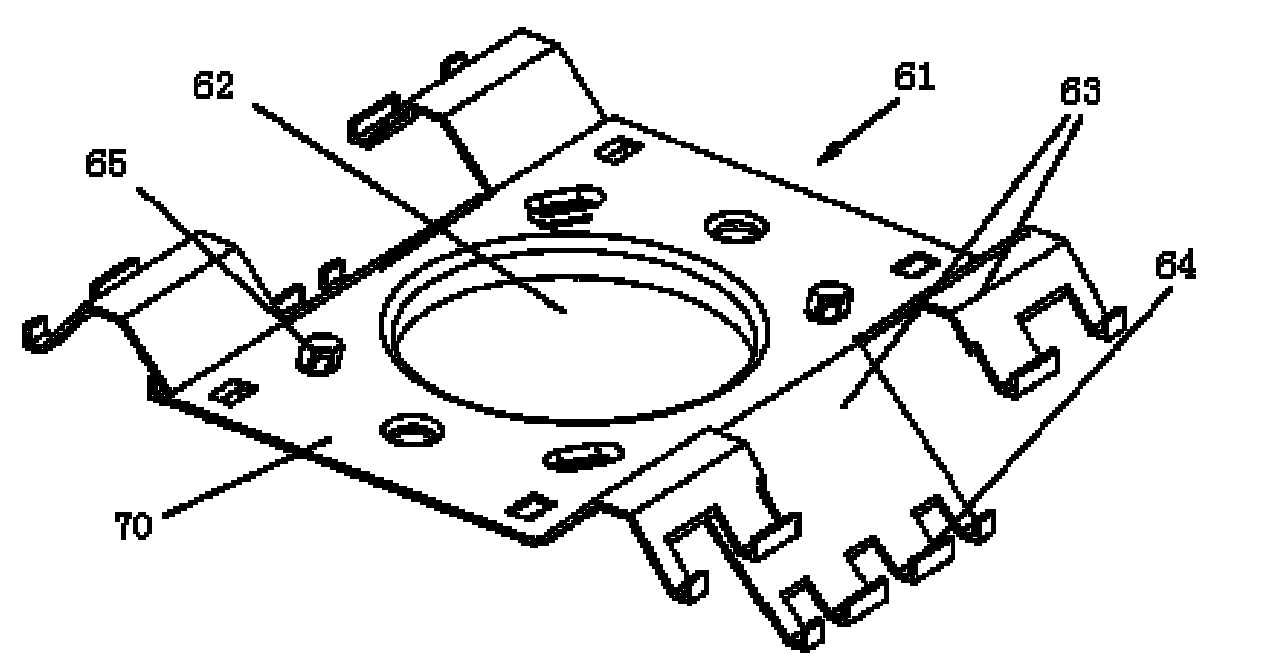
[0028] Such as Figure 4 As shown, the heat sink 61 of the magnetron of the present invention is integrally formed and stamped from an aluminum metal plate, and is divided into a main board 70 and cooling fins 63 arranged on both sides of the main board according to the position. An anode hole for assembling the magnetron anode shell 11 is left on the main board 70 in the middle of the heat sink. When the heat sink is installed, match the anode hole with the anode shell and press down into the heat sink. Repeat this step several times. A group of heat sinks of the same model can be stacked and installed on the same anode shell, and each heat sink is provided with a plurality of limiting protrusions (not shown). When installing, press each heat sink until...


PUM


Abstract

The invention relates to a radiating fin of a magnetron; the radiating fin is integrally formed by stamping a metal plate; an anode hole for assembling an anode shell of the magnetron is left on a main board forming the middle part of the radiating fin; the left side and the right side of the radiating fin are respectively sheared, bended and processed into a plurality of radiating blades so as to enlarge a contact area between the radiating fin and flowing air; the radiating blades at the left side and the right side are symmetrically distributed; flow guiding bugles are formed at the periphery of the anode hole on the main board; fixed bending is formed at the tail end of the outer side of each radiating blade; and the radiating fin is characterized in that the thickness of the main board in the middle part of the radiating fin is different from the thickness of the radiating blades arranged at both sides of the radiating fin; and the thickness of the main board is larger than that of the radiating blades. The radiating fin improves the heat conduction efficiency of the main board, more rapidly transmits more heat from the anode of the magnetron to the radiating fin and increases the convective heat exchange capacity of air current, so that the heat accumulated on the radiating fin is more rapidly diffused, thereby reducing the temperature of the anode of the magnetron and leads the working performance of the magnetron to be improved.

Description

technical field [0001] The invention belongs to the technical field of magnetrons, and in particular relates to a heat sink of a magnetron that increases the thickness of a main board while simultaneously reducing the thickness of heat dissipation blades on both sides of the main board, thereby effectively increasing heat exchange capacity and reducing the temperature of the anode of the magnetron. Background technique [0002] figure 1 It is a longitudinal sectional view of a magnetron structure in the prior art; figure 2 It is a structural schematic diagram of a magnetron heat sink in the prior art; image 3 is a side view of a heat sink of a prior art magnetron. [0003] Such as figure 1 , figure 2 As shown, the magnetron mainly includes: a positive electrode part; a negative electrode part; a magnetic pole part; and a microwave emitting part. The positive electrode part is composed of a barrel-shaped anode casing 11, and a plurality of radial blades 12 are formed ...

Claims


Application Information

Patent Timeline
Patent Type & Authority Applications(China)
IPC IPC(8): H01J23/033
Inventor 王影
Owner LG ELECTRONICS (TIANJIN) APPLIANCES CO LTD
Why Eureka
Try Eureka