

Electrode frame structure of redox flow battery
A technology of flow battery and electrode frame, which is applied to fuel cell parts, fuel cells, structural parts, etc., can solve the problem of difficulty in judging the placement direction of the electrode frame, and achieve low additional cost, easy identification, and simple and reasonable structure. Effect
Inactive Publication Date: 2011-08-10
DALIAN RONGKE POWER
View PDF3 Cites 5 Cited by
- Summary
- Abstract
- Description
- Claims
- Application Information
AI Technical Summary
Problems solved by technology
[0004] In order to solve the above problems in the structure of the flow battery, especially the difficulty in judging the direction of the electrode frame during assembly or after assembly
Method used
View moreImage
Smart ImageViewing Examples

Examples
Embodiment Construction
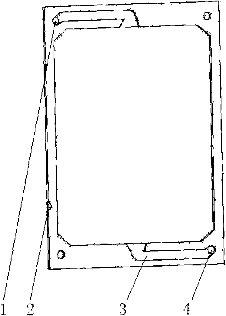
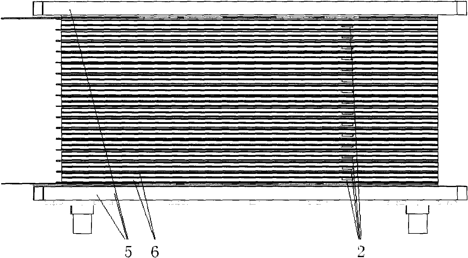
[0016] The structure of the electrode frame is as figure 1 As shown, the mark of the electrode frame is to process a 5mm semicircular groove with a depth of 2mm on the side of the electrode frame containing the flow channel, and on the long side where the electrolyte outlet is located. For this purpose during assembly (such as figure 2 ), the placement state of the electrode frame can be judged from the position and orientation of the groove of the electrode frame.
[0017] The electrode area: 225cm 2 , Number of single batteries: 15.
Login to View More PUM
| Property | Measurement | Unit |
|---|---|---|
| area | aaaaa | aaaaa |
Abstract
The invention relates to a structure of an energy storage battery, in particular an electrode frame structure of a redox flow battery, a mark is made in a specific position of an electrode frame, and the position of an outlet / inlet of the electrode frame and the facing direction of a flow passage groove can be rapidly judged during the assembly process or after the assembly. Therefore, errors during the assembly process can be effectively corrected and the stacking efficiency can be improved. The electrode frame structure is particularly applicable to battery stack structures with the same structure for positive and negative electrode frames or the same shape and the different placement directions.
Description
technical field [0001] The invention relates to the structure of an energy storage battery, in particular to an electrode frame structure of a redox flow battery. Background technique [0002] In order to protect human beings from the threat of climate warming, the "United Nations Framework Convention on Climate Change" imposes index restrictions on greenhouse gas emissions in various countries. For this reason, many countries gradually tilt their national energy development strategies towards renewable energy, such as wind energy, solar energy, and tidal energy. Wait. With the development of wind energy, solar energy, and tidal energy power generation scale, the proportion of their power generation increases, and the problems exposed thereby become more and more serious. In order to solve the contradiction between supply and demand caused by the discontinuous and sporadic characteristics of renewable energy power generation, large-scale energy storage has attracted the att...
Claims
Login to View More Application Information
Patent Timeline
 Patent Type & AuthorityApplications(China)
IPC IPC(8): H01M8/02H01M2/08H01M2/36H01M8/0271H01M8/0273H01M8/18
CPCY02E60/12Y02E60/50
Inventor高素军张华民韩希
OwnerDALIAN RONGKE POWER