Two-in-one coaxial direct current brushless motor

A DC brushless and motor technology, which is applied in the field of high-efficiency motors and two-in-one coaxial DC brushless motors, can solve problems such as dead angles still exist, large circuit space, and difficulty in starting, so as to simplify the parts and assembly process and facilitate processing Production, the effect of compact overall structure

Inactive Publication Date: 2011-08-10
湖州佳星电机有限公司
View PDF7 Cites 8 Cited by
  • Summary
  • Abstract
  • Description
  • Claims
  • Application Information

AI Technical Summary

Problems solved by technology

[0003] The number of stator teeth and the number of rotor magnetic poles of ordinary DC brushless motors are the same in number, and they are distributed symmetrically along the center of the rotating shaft; The neutral point is in the aligned phase, therefore, at the moment the motor starts, the force generated by the stator magnetic field and the rotor magnetic field reaches the maximum in the radial direction, but is zero in the circumferential direction, that is, the starting torque of the motor is zero, and the motor is difficult to start; and , when the motor is running, the moment the polarity of the stator is switched every time, the output torque of the motor is zero, so the DC brushless motor has a dead angle when it is locked during operation (Note: The DC brushless motor has no dead angle problem during operation); at the same time , since the maximum torque value of the motor is the maximum amplitude value of the torque, the torque changes greatly when the motor is running, the motor is easy to vibrate, and the running noise is large
[0004] Aiming at the problem that the brushless DC motor cannot be started, the current practice is to design the pole teeth of the stator as an asymmetrical shape on both sides, so that when the motor is stationary, the polarity teeth of the stator and the rotor magnet will attr...

Method used


Image

  • Two-in-one coaxial direct current brushless motor
  • Two-in-one coaxial direct current brushless motor
  • Two-in-one coaxial direct current brushless motor

Examples


Embodiment Construction

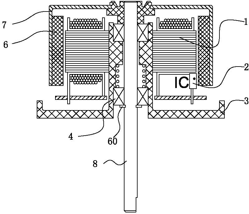
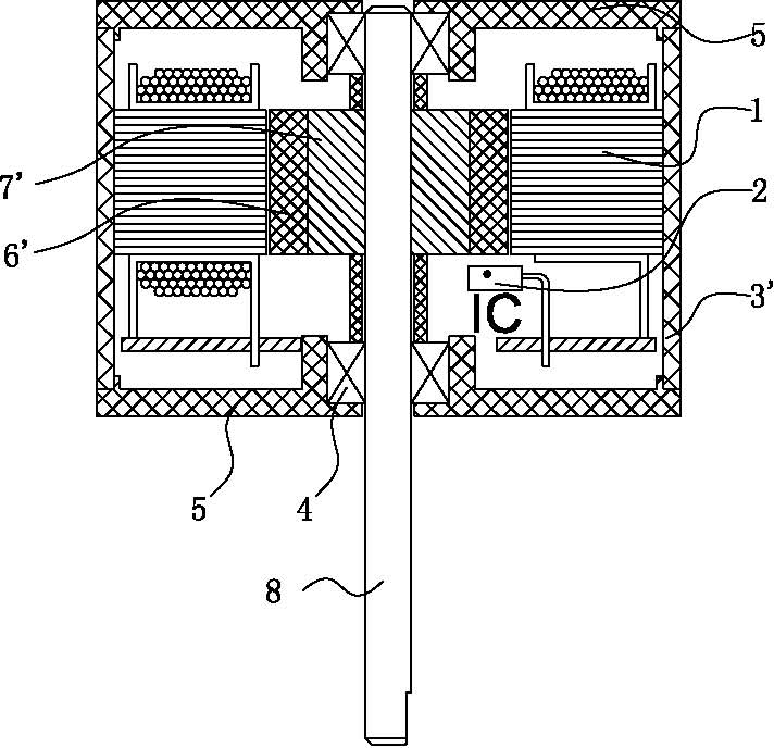
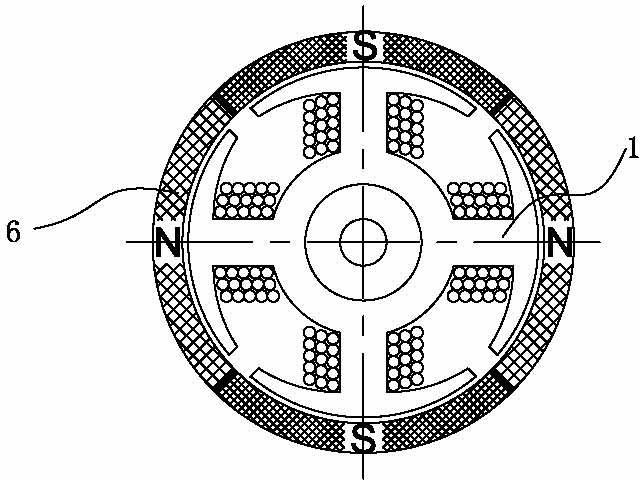
[0060] See Figure 5 to Figure 1 5, which shows the specific structure of the preferred embodiment of the present invention, including a common shaft 10, the first motor and the second motor coaxial (see Figure 5 or Figure 7 or Figure 14 ), the first motor and the second motor are both outer rotor brushless DC motors or inner rotor brushless DC motors, the output torque directions of the first motor and the second motor are the same, and the magnetic field polarity of the first rotor The relative phase of the midpoint and the midpoint of the first stator polarity teeth in radial projection is misaligned with respect to the relative phase of the radial projection of the second rotor's magnetic field polarity midpoint and the second stator polarity tooth midpoint, The misalignment angle is equal to 180° / number of stator teeth (see Figure 10a and Figure 10b shown or Figure 15a and Figure 15b shown);

[0061] Such as Figure 5 and Figure 6 As shown, it is the spec...


PUM


Abstract

The invention discloses a two-in-one coaxial direct current brushless motor which is an integrated motor composed of two direct current brushless motors with approximately equal power in a coaxial manner, wherein the performance of the integrated motor is obviously improved; the two-in-one coaxial direct current brushless motor comprises a public rotating shaft, a first motor, and a second motor;both the first motor and the second motor are the direct current brushless motors and arranged on the public rotating shaft in series; and by virtue of process control, the synthesized torque of the two-in-one coaxial direct current brushless motor is always more than zero when the two-in-one coaxial direct current brushless is started, and the minimum synthesized torque is the maximum torque of one of the motors, therefore, the torque amplitude of the whole motor is effectively reduced, the running of the motor is free from dead angles, the starting performance is better, the vibration caused by electromagnetic switching of the motor is reduced and the noise is reduced; and meanwhile, after being coaxially overlapped without changing the external diameter of the motors, the two motors can work simultaneously to achieve the effect of outputting a greater torque.

Description

technical field [0001] The present invention relates to the technology in the field of DC brushless motors, in particular to a high-efficiency motor with low cost and better performance, which is a two-in-one coaxial DC brushless motor that outputs superimposed torque through a common rotating shaft. Background technique [0002] Existing brushless DC motors usually include an outer rotor brushless DC motor (such as figure 1 shown) and inner rotor brushless DC motors (such as figure 2 shown) two types, they all include rotor assembly, stator assembly and connectors; the main parts of rotor assembly are permanent rotor magnet 6 (6'), rotor frame 7 (7') and shaft 8, etc., rotor frame 7 ( 7') is the main part connecting the rotating shaft 8 and the permanent rotor magnet 6 (6'), the position of the rotor magnet 6 (6') and the rotating shaft 8 is fixed after the connection and assembly, ( image 3 It is a schematic diagram of the mutual position of the stator and the rotor in...

Claims


Application Information

Patent Timeline
IPC IPC(8): H02K16/00H02K1/12H02K1/18H02K1/27H02K1/28H02P1/56
Inventor 高林发
Owner 湖州佳星电机有限公司
Why Eureka
Try Eureka