
Clamping pin positioning drilling machine and clamping pin positioning method

A positioning method and clamping pin technology, applied in the direction of the drilling mold used for workpieces, etc., can solve the problems of uneven hole bakelite, uneven loading, and easy bowing, etc., to improve drilling quality and reduce production costs , to avoid the effect of uneven loading

Inactive Publication Date: 2011-08-17
JIANGMEN SUNTAK CIRCUIT TECH
View PDF7 Cites 3 Cited by
  • Summary
  • Abstract
  • Description
  • Claims
  • Application Information

AI Technical Summary

Problems solved by technology

[0010] 1. Depending on the production volume, the bakelite board needs to be replaced. Due to the high cost of the bakelite board, the drilling cost of the product is high;
[0011] 2. It takes a long time to produce the upper and lower plates, that is, it takes a long time to process the drilling machine, which makes the utilization rate of the drilling machine (the ratio of production and processing time to the total start-up time) low;
[0012] 3. When drilling positioning holes on the bakelite board or when dialing the positioning pins, the holes are prone to peaks and cause the bakelite board to be uneven, making the board uneven and affecting the quality of the drilling (drilling off the hole or breaking the drill bit);
[0013] 4. Bakelite boards are prone to bowing due to moisture absorption during use, which affects the drilling quality;
[0014] 5. Powder chips often appear when drilling positioning holes on bakelite boards, making the board uneven and affecting the drilling quality

Method used


Image

  • Clamping pin positioning drilling machine and clamping pin positioning method
  • Clamping pin positioning drilling machine and clamping pin positioning method

Examples


Embodiment Construction

[0040] The present invention will be further described below in conjunction with the accompanying drawings and specific embodiments.

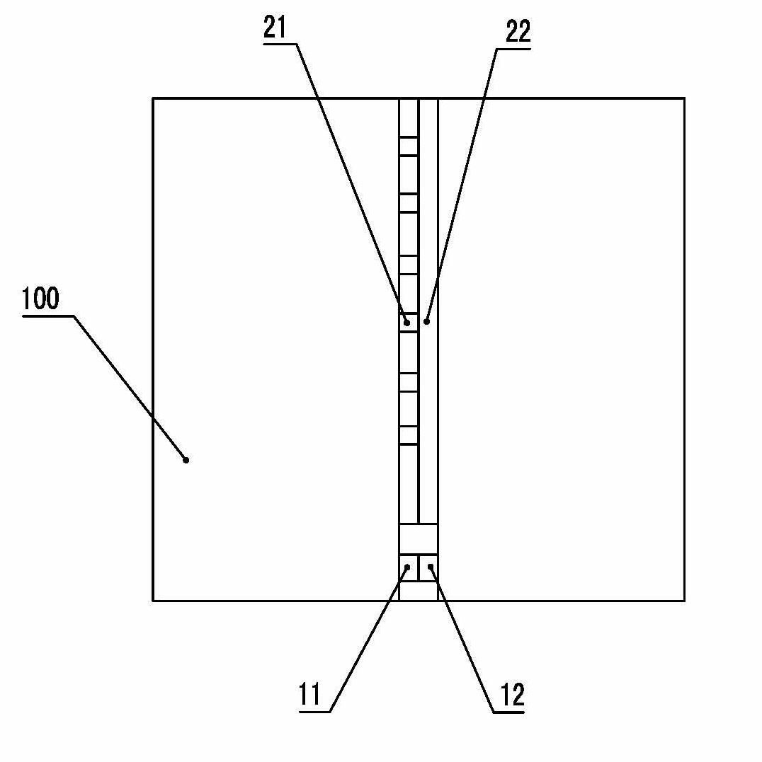
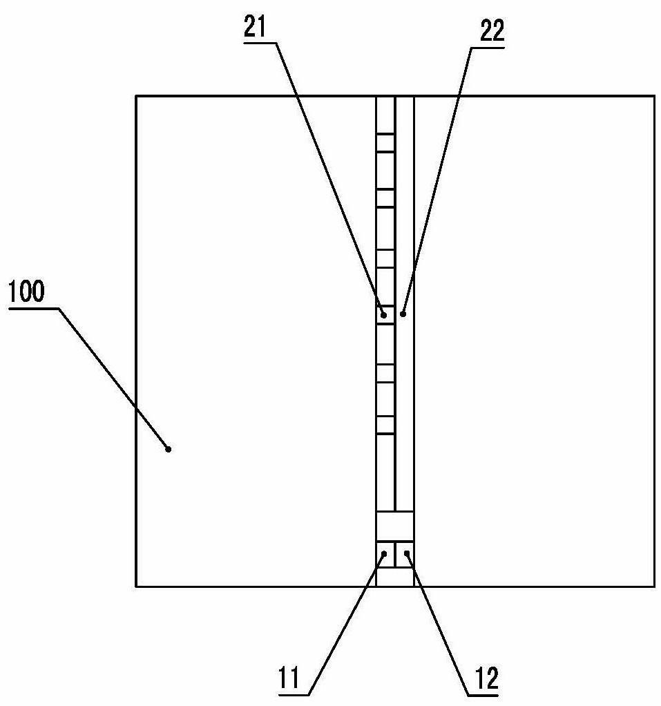
[0041] figure 1 The reference numerals in the figure are: workbench 100 ; origin positioning hole 11 ; first positioning slider 12 ; positioning slot 21 ; second positioning slider 22 .

[0042] Such as figure 1 As shown, a clamping pin positioning drilling machine includes a workbench 100, the workbench 100 is provided with an origin positioning hole 11 and a positioning groove 21 of a clamping pin, and the origin positioning hole 11 is collinear with the positioning groove 21, The origin positioning hole 11 is provided with a first positioning slider 12, and the first positioning slider 12 is connected with a first pushing and clamping mechanism. The positioning groove 21 is provided with a second positioning slider 22. The second positioning slide block 22 is connected with a second pushing and clamping mechanism.

[0043] Such as figure...


PUM


Abstract

The invention relates to a printed circuit, in particular to a clamping pin positioning drilling machine and a clamping pin positioning method. The clamping pin positioning drilling machine provided by the invention comprises a working platform; the working platform is provided with an origin positioning hole and a positioning groove of a clamping pin; the origin positioning hole and the positioning groove are collinear; the origin positioning hole is internally provided with a first positioning sliding block which is connected with a first pushing and clamping mechanism; and the positioning groove is internally provided with a second positioning sliding block which is connected with a second pushing and clamping mechanism. The invention also provides the clamping pin positioning method and has the benefits that an electric wood board does not need to be used, the production cost is reduced, the unsmooth plate installation is avoided, the drilling quality is improved, processes performed on the drilling machine are reduced and the utilization rate is improved.

Description

technical field [0001] The invention relates to a printed circuit, in particular to a clamping pin positioning drilling machine and a clamping pin positioning method in the printed circuit. Background technique [0002] At present, when drilling printed circuit boards, the positioning method of bakelite is used for positioning and drilling. The so-called bakelite positioning method is to set a bakelite board on the workbench of the drilling machine and fix it with screws. The printed circuit board is drilled and produced. When using the positioning hole program of the printed circuit board to be processed, first drill the positioning holes of the printed circuit board to be processed on the bakelite board (generally three for multi-layer boards, and two for double-sided boards), and then install the pins , and finally stack the backing board and the printed circuit board to be processed in turn, and then put the aluminum sheet on it, fix the aluminum sheet with tape, and the...

Claims


Application Information

Patent Timeline
Patent Type & Authority Applications(China)
IPC IPC(8): B23B47/28
Inventor 韦昊陈国忠张庭主邓峻
Owner JIANGMEN SUNTAK CIRCUIT TECH
Learn More