Traceless laser correction method for back deformation of stainless steel plate subjected to non-penetration laser welding

A technology of laser welding and stainless steel plate, which is applied in the field of laser heat treatment, to avoid discoloration and restore smoothness on the back surface of the outer plate

Inactive Publication Date: 2011-08-17
CHANGCHUN UNIV OF SCI & TECH
View PDF5 Cites 8 Cited by
  • Summary
  • Abstract
  • Description
  • Claims
  • Application Information

AI Technical Summary

Problems solved by technology

For this reason, we propose a non-penetrating laser welding method for back deformation

Method used


Image

  • Traceless laser correction method for back deformation of stainless steel plate subjected to non-penetration laser welding
  • Traceless laser correction method for back deformation of stainless steel plate subjected to non-penetration laser welding
  • Traceless laser correction method for back deformation of stainless steel plate subjected to non-penetration laser welding

Examples


Embodiment 1

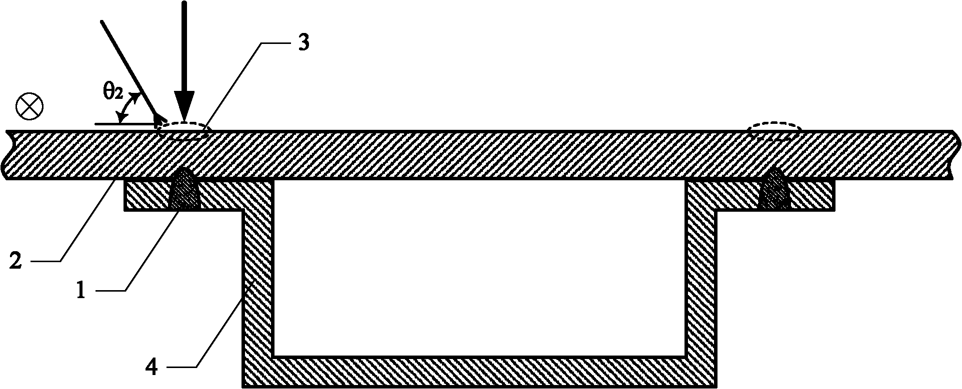
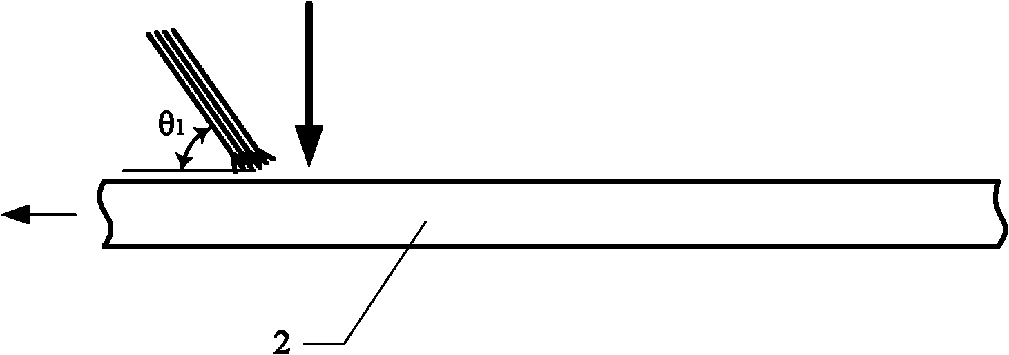
[0010] Clean the deformed area 3 on the back of the stainless steel body panel 2 of the rail passenger car with acetone to remove surface oil. The outer plate 2 and the outer plate reinforcing member 4 are made of SUS301L cold-rolled stainless steel plate, the thickness of the outer plate 2 is 1.5mm, the thickness of the outer plate reinforcing member 4 is 0.8mm, and the penetration depth is 1.0mm. See figure 1 , figure 2 shown, with quasi-fundamental CO 2 The laser is the heat source, the laser power is 80W, and the defocus is +4mm. Move and heat the deformed area 3 on the back of the stainless steel car body panel 2 of the rail car along the direction of the weld 1 at a moving speed of 0.5m / min. Blow protective gas N into the heated area at the same time 2 . The protective gas is blown in after the laser heating; the protective gas is composed of 4 parallel airflows arranged in a line along the laser heating moving direction; the protective gas blowing direction and th...

Embodiment 2

[0012] Clean the deformed area 3 on the back of the stainless steel body panel 2 of the rail passenger car with acetone to remove surface oil. The outer plate 2 and the outer plate reinforcement member 4 are made of SUS304 cold-rolled stainless steel plate, the thickness of the outer plate 2 is 2.0mm, the thickness of the outer plate reinforcement member 4 is 1.0mm, and the penetration depth is 1.2mm. See figure 1 , figure 2 As shown, the fundamental mode YAG laser is used as the heat source, the laser power is 100W, and the defocus amount is +2mm. Move and heat the deformed area 3 on the back of the stainless steel car body panel 2 of the rail car along the direction of the weld seam 1 at a moving speed of 0.3m / min. At the same time, the protective gas Ar is blown into the heated area. The protective gas is blown in after the laser heating; the protective gas is composed of 5 parallel airflows arranged in a line along the moving direction of the laser heating; the blowing...


PUM


Abstract

The invention discloses a traceless laser correction method for back deformation of a stainless steel plate subjected to non-penetration laser welding and belongs to the technical field of laser heat treatment. Abrasive machining is performed on the back of an external plate before or after non-penetration laser welding in the prior art to form surface wire drawing lines, so the deformation of the back of the external plate can be covered visually; by the prior art, the deformation cannot be corrected sensibly; the wire drawing lines cannot cover the welding deformation in different directions; the covering and the welding deformation in the same direction only become unclear visually. In the traceless laser correction method, laser is used as a heat source to movably heat a deformed region of the back of the external plate of a stainless steel railway vehicle body along the direction of a welding line; meanwhile, a protective gas is blown into the heated region; the mobile heating time is greater than or equal to one; and the moving direction of the heat source for each time of heating is the same. By the traceless laser correction method, traceless correction for the back deformation of the stainless steel plate of the railway vehicle subjected to non-penetration laser welding can be realized.

Description

technical field [0001] The invention relates to a traceless laser correction method for back deformation after non-penetration laser welding of a stainless steel plate, which is used for the traceless correction of back deformation after non-penetration laser welding of a rail passenger car body stainless steel plate, and belongs to the technical field of laser heat treatment. Background technique [0002] Urban subway, light rail and railway traffic use a large number of rail passenger cars. Compared with ordinary steel or aluminum alloy car bodies, the stainless steel car bodies of rail cars have the advantages of economy, durability, beauty, safety, and no need for coating on the outer surface. The demand is increasing. bigger and bigger. Stainless steel body panels are made of SUS301L or SUS304 cold-rolled stainless steel plates with beautiful surfaces, of which SUS301L accounts for 70%. In the prior art, the non-penetrating laser welding method is used to realize the j...

Claims


Application Information

Patent Timeline
IPC IPC(8): B23K26/14B23K26/142
Inventor 张宏刘佳石岩刘双宇
Owner CHANGCHUN UNIV OF SCI & TECH
Why Eureka
Try Eureka