
Time synchronizing method capable of recognizing GPS input signals in self-adapting manner

An input signal, self-adaptive technology, applied to radio-controlled timers, clocks driven by synchronous motors, electronic timers, etc., can solve the problem of abnormal operation of automatic devices, increased system complexity, and error-prone relay protection, etc. problem, to achieve the effect of simple setting, convenient implementation and strong applicability

Active Publication Date: 2011-08-17
STATE GRID ELECTRIC POWER RES INST
View PDF4 Cites 13 Cited by
  • Summary
  • Abstract
  • Description
  • Claims
  • Application Information

AI Technical Summary

Problems solved by technology

[0005] (2) Time message, including time information and other information, there is no unified format at present, and RS-232 serial port is generally used for transmission;
In these methods, either cannot flexibly adapt to the needs of the site, are prone to errors and make the relay protection and automatic devices work abnormally, or increase the complexity of the system and increase the cost

Method used


Image

  • Time synchronizing method capable of recognizing GPS input signals in self-adapting manner
  • Time synchronizing method capable of recognizing GPS input signals in self-adapting manner
  • Time synchronizing method capable of recognizing GPS input signals in self-adapting manner

Examples


Embodiment Construction

[0029] The present invention will be further described in detail below with reference to the accompanying drawings and examples. However, the invention is not limited to the examples given.

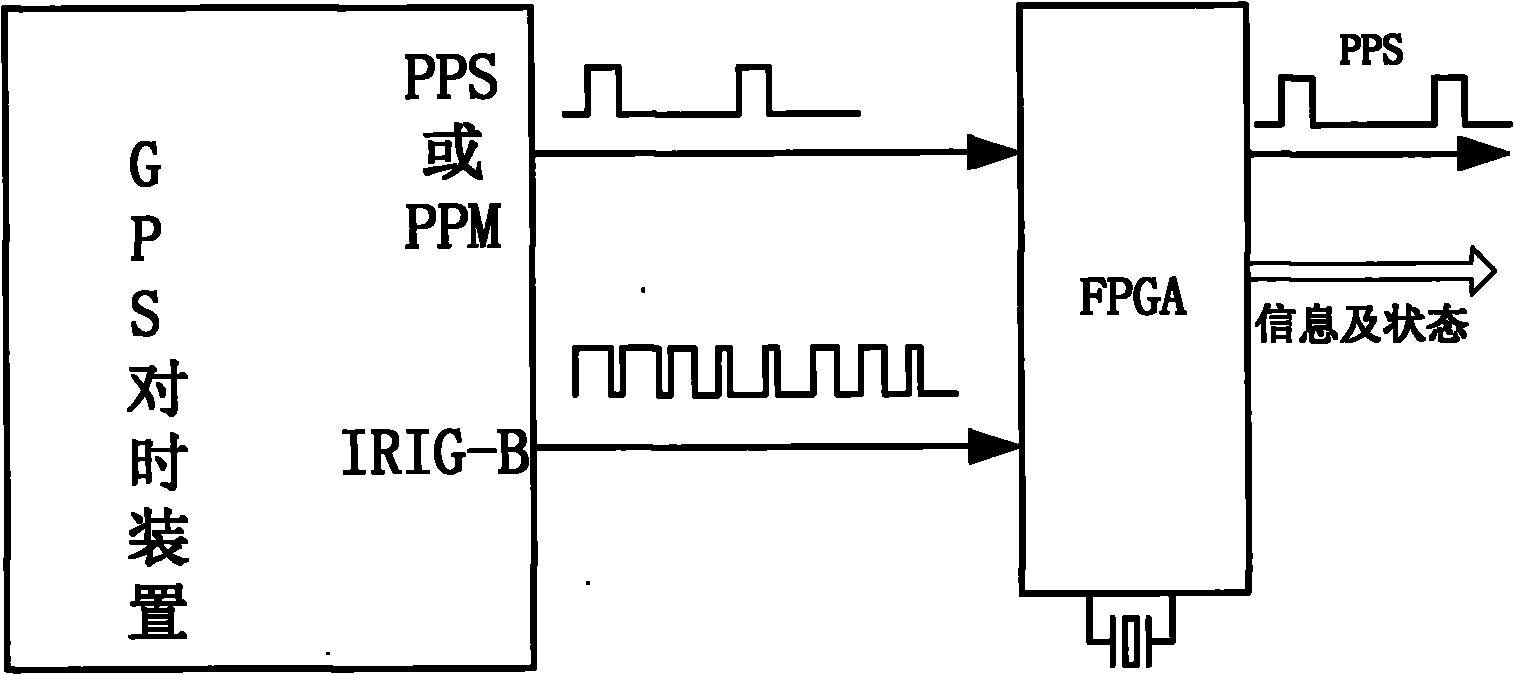
[0030] Such as figure 1 As shown, it is a schematic diagram of the hardware involved in the system of the present invention. The GPS time synchronization device outputs PPS or / and PPM or / and IRIG-B signals and inputs them to FPGA. Since the output voltage of the GPS time synchronization device is about 12V, it exceeds FPGA Acceptable range, so the signal must be conditioned so that the GPS timing signal is adjusted to a TTL or LVTTL signal that the FPGA can accept. After the FPGA processes the input timing signal, it sends the PPS pulse to the processing system, and related Real-time information and status, which facilitates more accurate control of the processing system.

[0031] Due to its flexibility, FPGA has been used more and more in electronic devices, and the reliability of this...


PUM


Abstract

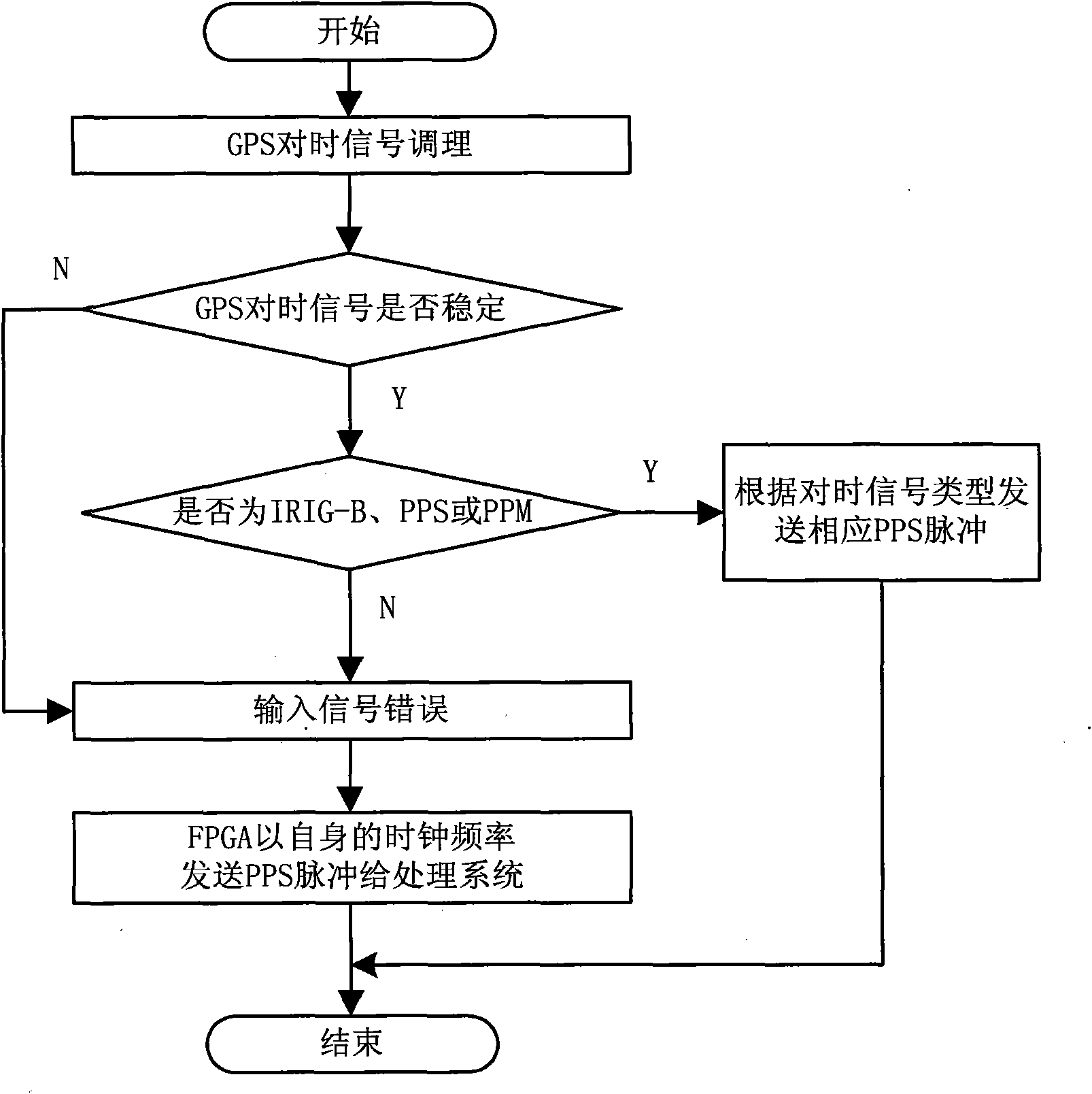
The invention discloses a time synchronizing method capable of recognizing GPS input signals in a self-adapting manner, relating to a technology for realizing precise time synchronization for a relay-protection and automatic device of an electric power system by utilizing a GPS. In the method, GPS time-synchronizing signals are judged and are unified to be synchronous PPS (Pulse Per Second) signals to be transmitted, thus the self-adaptation of various GPS time-synchronizing signals can be realized, and a set of equipment can be suitable for various situations and has strong applicability, so that the investment of the equipment is reduced. The function is realized by utilizing an FPGA (Field Programmable Gate Array) existing in the equipment, and the problem that transformer substations utilize different types of GPS time-synchronizing information is solved on the premise of not increasing any hardware costs. When an IRIG-B (Inter-Range Instrumentation Group-B) signal and a pulse signal exist at the same time, the IRIG-B signal containing more information content is preferably selected as the reference to carry out corresponding PPS pulse output, thus the stability and the precision of the electric power system are improved. In addition, the PPS pulse transmission can be carried out according to an original clock under the condition that the GPS signals are lost so that the system can be ensured to run normally.

Description

technical field [0001] The invention relates to a time synchronization method for adaptively identifying GPS input signals. Background technique [0002] Various automation devices are installed in the modern power system, such as the measurement and control unit of the monitoring system, RTU, fault recorder, microcomputer protection device, SCADA, and so on. These devices have real-time clocks inside, but these clocks will inevitably have errors. If they are not calibrated in time, the errors will accumulate and become larger and larger. In the power system, automatic information transmission, relay protection and automatic devices all need an accurate and unified clock. Based on this unified time base, when an abnormality or fault occurs in the power system, the waveform provided by the unified clock is of reference value, and can correctly judge the cause of the fault, the sequence of actions of various protections and automatic devices, and the evolution and evolution o...

Claims


Application Information

Patent Timeline
Patent Type & Authority Applications(China)
IPC IPC(8): G04G7/02G04R20/06
Inventor 姚吉文周华良夏雨徐建松姜雷郑玉平
Owner STATE GRID ELECTRIC POWER RES INST
Learn More