Mutual coupling compensation analysis method for microstrip array antenna

An array antenna and array technology, applied in the field of mutual coupling compensation analysis of microstrip array antennas, can solve problems such as side lobe rise, signal-to-noise ratio drop, and antenna not reaching the best design effect

Inactive Publication Date: 2011-08-17
宗鹏 +1
View PDF0 Cites 15 Cited by
  • Summary
  • Abstract
  • Description
  • Claims
  • Application Information

AI Technical Summary

Problems solved by technology

The mutual coupling effect of the antenna directly affects the change of the electrical parameters of the antenna performance. For example, if the current distribution changes, the input impedance and gain will also change, causing the radiation pattern to be distorted, the main beam direction to shift, and the side lobe to rise. SNR drop
In short, the existence of the mutual coupling effect of the antenna makes the antenna not reach the best design effect

Method used


Image

  • Mutual coupling compensation analysis method for microstrip array antenna
  • Mutual coupling compensation analysis method for microstrip array antenna
  • Mutual coupling compensation analysis method for microstrip array antenna

Examples


Embodiment Construction

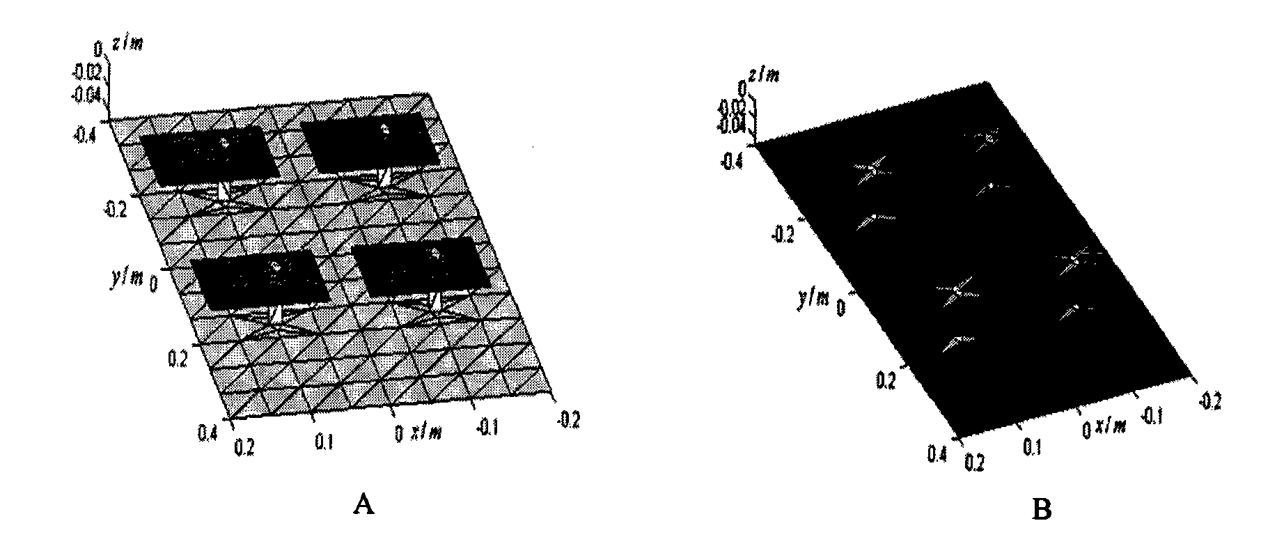
[0012] Mutual-coupling analysis of array antennas: First, model the structure of the array antenna, use the MATLAB function delaunay to triangulate the structure, divide the surface of the metal to be studied into a series of triangles, and each pair of triangles with a common side Constitute the corresponding RWG edge elements. Then, using the dipole model method, the surface current distribution of the RWG edge element containing two triangles is replaced by an infinitesimal dipole with equivalent dipole moment or strength, and the electromagnetic field of free space is determined for its surface current radiation properties.

[0013] The surface current of the array patch based on Matlab programming simulation is shown in Figure 1A. In the schematic diagram of the surface current of the patch, the lighter the color, the larger the surface current of the patch. It can be generally seen that there is a larger current density at the patch, as shown in Figure 1B. It can be se...


PUM


Abstract

The invention discloses a mutual coupling compensation analysis method for a microstrip array antenna. The method comprises the following steps of: modeling an array antenna structure, and performing delaunay triangulation on the structure by using the delaunay of a MATLAB function to divide the surface of a metal to be researched into a series of triangles, wherein each pair of triangles with common sides forms corresponding Rao-Wilton-Glisson (RWG) side elements; and replacing the surface current distribution of the RWG side elements of two triangles by using an infinitesimal dipole with an equivalent dipole moment or strength by adopting a dipole modeling method, and determining the electromagnetic radiation characteristics of a free space for surface current. A mutual impedance array, solved by adopting a moment method, of the microstrip array antenna takes the effect of mutual coupling between adjacent radiation elements into account. Therefore, a mutual coupling weight vector of an array unit is corrected during weight vector calculation mutual coupling effect correction to further optimize the output direction characteristics of an array.

Description

[0001] The surface current distribution of the array element is an important parameter for analyzing the array antenna, which determines the array radiation and scattering characteristics. There are many methods to analyze this characteristic, among which the method of moments is the most typical one. The most commonly used basis function in the method of moments is the impulse basis function, which is matched with point matching, which requires more sampling points, which increases the amount of calculation, and it cannot effectively represent some vector functions. [0002] The RWG (Rao-Wilton-Glisson) edge element method divides the antenna surface into many triangular small units. The triangular patch can satisfy the solution of any shape or boundary conductor. The changing conductor surface current density can be obtained in the small triangular patch Expressed conveniently and intuitively. The scope of RWG edge elements is a triangular area, which is easier to conform to ...

Claims


Application Information

Patent Timeline
Patent Type & Authority Applications(China)
IPC IPC(8): H01Q13/08H01Q21/00
Inventor 张青宗鹏
Owner 宗鹏
Why Eureka
Try Eureka