Passive Q-switched all-fiber laser

An all-fiber and laser technology, applied in the field of lasers, can solve the problems of increasing system loss and complexity, increasing system cost and energy consumption, and achieving the effects of improving stability, reducing high loss, and reducing costs

Inactive Publication Date: 2011-08-17
INST OF IND TECH GUANGZHOU & CHINESE ACADEMY OF SCI
View PDF1 Cites 7 Cited by
  • Summary
  • Abstract
  • Description
  • Claims
  • Application Information

AI Technical Summary

Problems solved by technology

Due to the use of acousto-optic devices, corresponding RF drive circuits need to be equipped, which increases system loss and complexity, and also increases system cost and energy consumption

Method used


Image

  • Passive Q-switched all-fiber laser
  • Passive Q-switched all-fiber laser
  • Passive Q-switched all-fiber laser

Examples


Embodiment 1

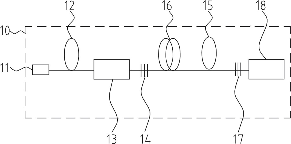
[0022] The structural schematic diagram of the passive Q-switched all-fiber laser of this embodiment is as follows figure 1 As shown, the passively Q-switched all-fiber laser is only composed of an oscillation stage 10, and the oscillation stage 10 is composed of a pump source 11, a pump protector 12, a coupler 13, a first grating 14, and a first doped fiber 16 arranged in sequence. , a Q-switching element 15, a second grating 17 and an isolator 18, wherein the pumping source 11 is a single-mode semiconductor laser with pigtail output. Pump protector 12 is Sm 3+ Saturable absorber fiber, using Sm 3+ The absorption characteristics of the filter filter out the ASE light generated by the first doped fiber 16 in the resonant cavity to complete the protection of the pumping source 11. The coupler 13 is used to couple the single-mode signal light into the resonant cavity. The first grating 14 is an FBG grating, which has the characteristics of high transparency to pump light and ...

Embodiment 2

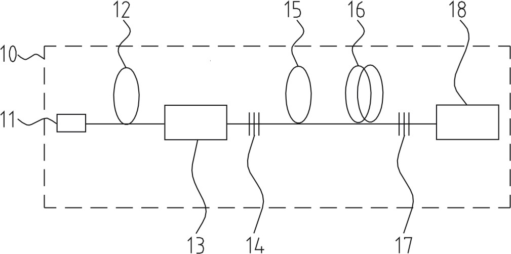
[0025] Such as figure 2 As shown, the difference from Embodiment 1 is that the Q-switching element is immediately in front of the first doped fiber. Compared with Embodiment 1, the output power of the pulse signal obtained in this embodiment is smaller and the pulse period is longer.

Embodiment 3

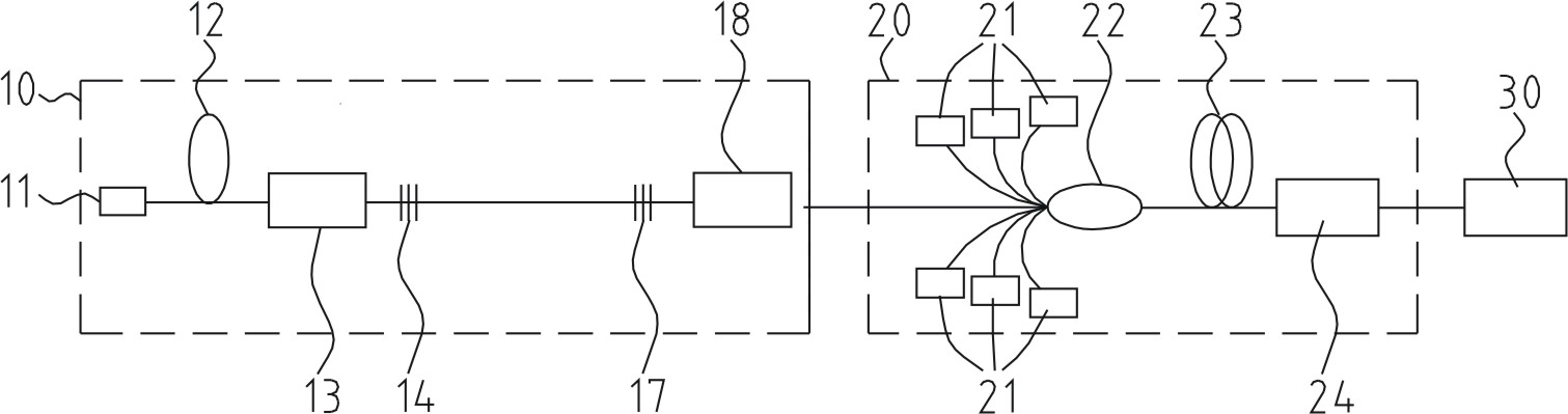
[0027] Such as image 3 As shown, the difference from Embodiment 1 is that a power amplification stage 20 is provided after the oscillation stage to amplify the power of the pulsed laser output from the oscillation stage and then output it. The power amplification stage 20 is composed of a pumping source group 21, a beam combiner 22, a second doped fiber 23 and an isolator 24, wherein the pumping source group 21 can use a laser diode with a tail output, and its selection mainly considers the second The absorption characteristics of doped fibers and the stability of the system. The beam combiner 22 is a (n+1)*1 beam combiner including (1+1)*1, (2+1)*1, (6+1)*1, etc., and the optical fiber at the pump end and the pump source The pigtails of the group 21 are matched, the signal input end needs to match the output fiber of the oscillator stage, and the signal output end fiber needs to match the second doped fiber 23, so that the system can obtain the best transmission characteris...


PUM


Abstract

The invention discloses a passive Q-switched all-fiber laser which comprises an oscillator stage. The oscillator stage comprises a pumping source, a coupler, a first grating, a first doped fiber, a Q-switched element and a second grating, wherein the Q-switched element is an Sm<3+> saturable absorber fiber, and the Q-switched element is closely arranged before or behind the first doped fiber. In the passive Q-switched all-fiber laser provided by the invention, the Sm<3+> saturable absorber fiber is used as a passive Q-switched element. Compared with the active Q-switched scheme of AOM (Acoustic Optical Modulator), in the passive Q-switched all-fiber laser provided by the invention, radio frequency drive is omitted in the AOM, and system complexity and high losses caused by an AOM element are reduced, meanwhile, the cost is greatly reduced, the system structure is simplified and the system stability is improved, so that producibility is easier to realize.

Description

technical field [0001] The invention relates to a laser, in particular to a passive Q-switched all-fiber laser. Background technique [0002] At present, high-power pulsed fiber lasers mainly amplify low-power pulsed optical signals in the subsequent optical path, and the generation of pulsed signal light is mainly completed by active acousto-optic modulation (AOM). Active acousto-optic modulation is to use acousto-optic crystals to change the gain in the cavity to convert continuous light into pulsed light output. Due to the use of acousto-optic devices, corresponding radio frequency drive circuits need to be equipped, which increases system loss and complexity, and also increases system cost and energy consumption. Contents of the invention [0003] The object of the present invention is to overcome the defects of the prior art and provide a passive Q-switched all-fiber laser with simple structure, high stability, low cost and easy maintenance. [0004] A passive Q-swi...

Claims


Application Information

Patent Timeline
Patent Type & Authority Applications(China)
IPC IPC(8): H01S3/067H01S3/106H01S3/11H01S3/00
Inventor 杜卫冲邓永丽
Owner INST OF IND TECH GUANGZHOU & CHINESE ACADEMY OF SCI
Why Eureka
Try Eureka