
Lower-than-lower-limit reverse control time base circuit

A time-based circuit and circuit technology, applied in circuit devices, emergency protection circuit devices, electrical components, etc., can solve the problems of not being able to cut off the load power supply in time, improper reset potential setting, and potential safety hazards in use, and achieve both fault protection and display functions , prevent failure out of control, easy to apply

Inactive Publication Date: 2011-08-17
刘圣平
View PDF4 Cites 4 Cited by
  • Summary
  • Abstract
  • Description
  • Claims
  • Application Information

AI Technical Summary

Problems solved by technology

[0005] The invention mainly solves the technical problems that the original main control (super upper and lower limit control) circuit and the timing circuit are often out of control due to abnormal faults, the load power supply cannot be cut off in time, and there are potential safety hazards in use; it provides a device that can monitor abnormal faults and has The bottom anti-control protection function prevents the main control circuit from getting out of control, cuts off the load power supply in time, avoids serious accidents (such as fire), and ensures the safe use of the bottom anti-control time base circuit
[0006] The present invention simultaneously solves the technical problems that the reset potential of the reset terminal of the original over-limit control function circuit is improperly set, and the dispersion is too large and the performance is not good; it provides a reset function that doubles as a protection display and a vibration elimination function, reducing the dispersion Sex, improve the performance of the bottom anti-control time base circuit

Method used


Image

  • Lower-than-lower-limit reverse control time base circuit
  • Lower-than-lower-limit reverse control time base circuit
  • Lower-than-lower-limit reverse control time base circuit

Examples


Embodiment 1

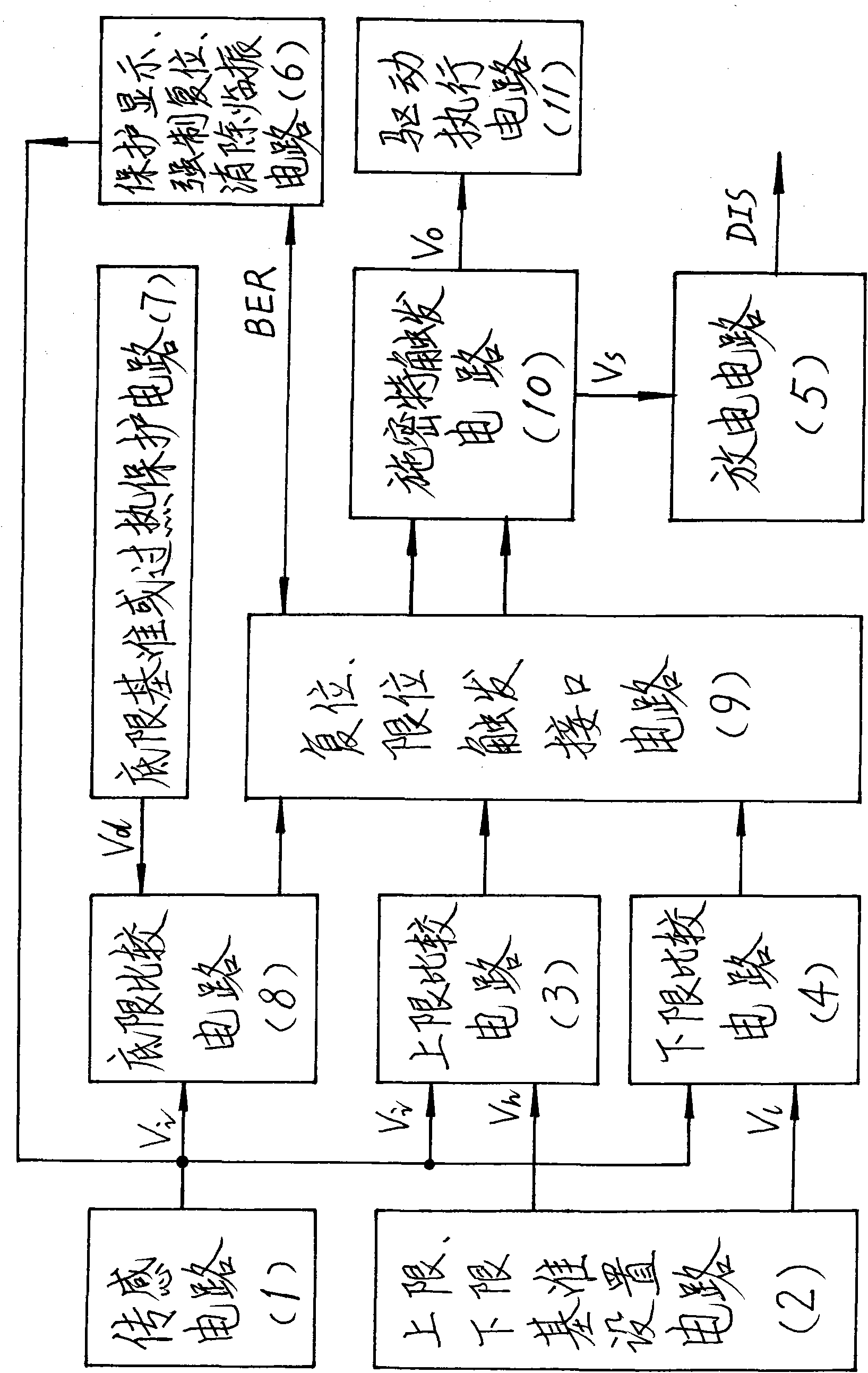
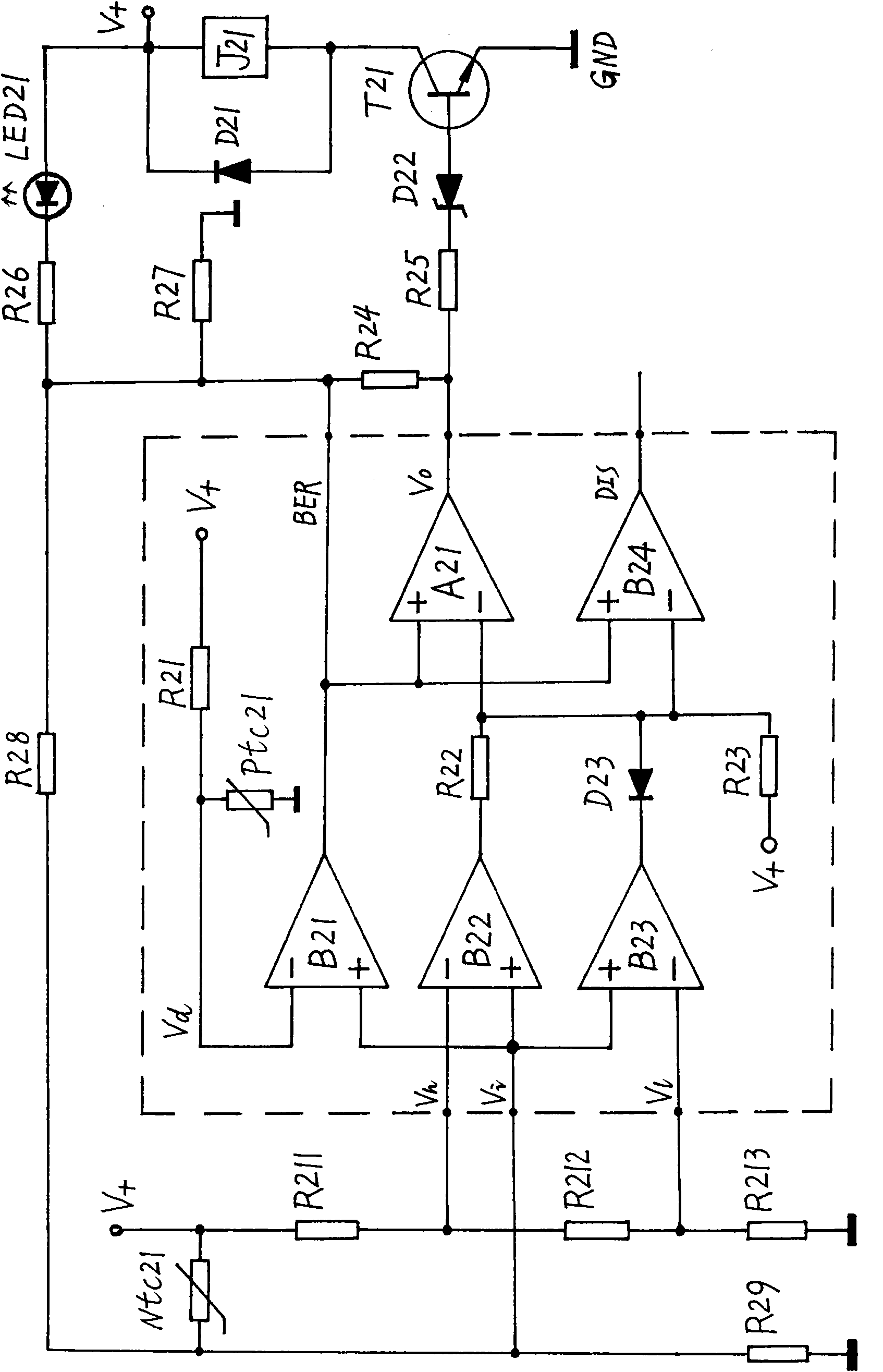
[0023] The circuit block diagram of embodiment 1 and embodiment 2, as figure 1 As shown, (1) is the sensing circuit, (2) is the upper and lower limit reference setting circuit, (3) is the upper limit comparison circuit, (4) is the lower limit comparison circuit, (5) is the discharge circuit, and (6) is the protection display / force reset / eliminate the impending vibration circuit, (7) is the bottom limit reference or overheating protection circuit, (8) is the bottom limit comparison circuit, (9) is the reset / limit trigger interface circuit, (10) is the Schmitt trigger Circuit, (11) is the driving executive circuit.

[0024] The sensing signal input terminal (V i ) and the two input terminals (V i ) in parallel at the same point, and then connect the output terminal of the sensing circuit (1); the reference potential (V h ), and the reference potential (V L ) is provided by the upper limit / lower limit reference setting circuit (2), and the bottom limit reference potential (V...

Embodiment 2

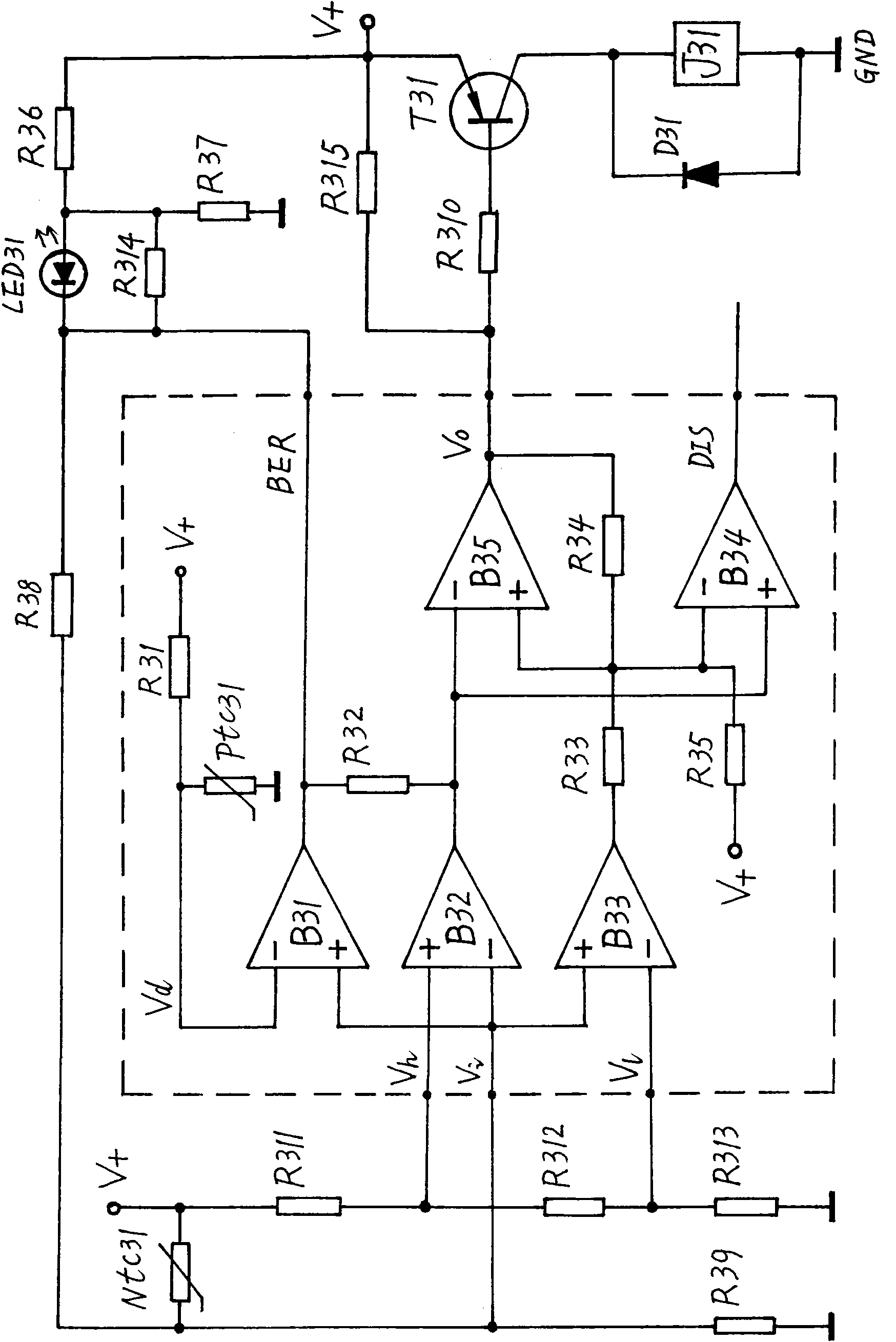
[0035] This embodiment is also an example of the application of a temperature control circuit. The specific circuit schematic diagram is as follows: image 3 As shown, the sensing circuit (1) includes a negative temperature coefficient thermistor Ntc31 and a resistor R39, and the upper / lower limit reference setting circuit (2) includes resistors R311, R312, R313, and the upper limit comparison circuit (3) is voltage comparator B32, and described lower limit comparator circuit (4) is voltage comparator B33, and described discharge circuit (5) is voltage comparator B34, and described protection display / forced reset / eliminate temporary vibration Circuit (6) comprises light-emitting diode LED31 and resistance R314, R36, R37, R38, and described bottom reference or overheat protection circuit (7) comprises positive temperature coefficient thermistor Pt C 31 and resistor R31, the bottom limit comparator circuit (8) is a voltage comparator B31, and the reset / limit trigger interface ci...


PUM


Abstract

The invention relates to lower-than-lower-limit reverse control time base circuit. All functions of a 555 time base circuit are completely compatible, and new functions are expanded. The technical problem that a conventional master control circuit for higher-than-upper-limit control and lower-than-lower-limit control and a timing circuit are out of control due to failures and cannot timely cut power supplied to a load off to cause potential safety hazards. The technical scheme is that: a lower limit reference circuit, a comparison circuit and a triggering protection circuit are arranged; when a sensing circuit abnormally fails, the inversion of a post-stage circuit is preferably triggered, and a lower-than-lower-limit reverse control protection function is realized to forcibly cut the power supplied to the load off and reliably prevent the failures from causing uncontrollability. When applied to temperature, pressure, water level and timing control circuits, the lower-than-lower-limit reverse control time base circuit can improve the safety performance and avoid serious accidents such as fire when in use. Therefore, the lower-than-lower-limit reverse control time base circuit has high practical value and higher cost performance, and is more widely applied in the fields of electronic application such as small home appliance and simple measurement, timing, control, safety protection and the like.

Description

technical field [0001] The present invention relates to a control circuit / time base circuit, in particular to a time base circuit that ensures that the main control (super upper and lower limit control) or the timing control circuit does not get out of control when the timing control circuit fails. It is applied in temperature, pressure, In water level and timing control electrical appliances, it can improve safety performance and avoid serious accidents (such as fire) during use. Therefore, the present invention has wider applications in electronic application fields such as small household appliances and simple measurement, timing, control, and safety protection, and makes electrical products more cost-effective. Background technique [0002] In order to verify the novelty of the present invention, the designer consulted a large number of relevant technical materials (professional books, newspapers and periodicals), and retrieved relevant patent documents. It is only foun...

Claims


Application Information

Patent Timeline
Patent Type & Authority Applications(China)
IPC IPC(8): H02H7/00H02H3/02H02H5/04
Inventor 刘圣平
Owner 刘圣平
Learn More