Novel direct-current converter valve thyristor damping loop

A technology of DC converter valves and thyristors, applied in the direction of output power conversion devices, electrical components, etc., can solve problems such as the gate plate voltage cannot be satisfied, there is no fast energy-taking circuit, and the probability of problems increases, so as to achieve the design idea Clear, functional, improved damping loop effect

Active Publication Date: 2011-08-17
CHINA ELECTRIC POWER RES INST +1
View PDF3 Cites 10 Cited by
  • Summary
  • Abstract
  • Description
  • Claims
  • Application Information

AI Technical Summary

Problems solved by technology

The damping loop is composed of two loops. This design method can ensure that the two damping loops are used to obtain energy, so that the electric energy of the gate plate can be maintained for a long time, but this design method makes the damping loop slightly complicated. The design of this circuit increases the probability of problems in actual engineering, and such a damping circuit design does not have a fast energy harvesting circuit, which cannot satisfy the gate plate to establish a working voltage in a short period of time

Method used


Image

  • Novel direct-current converter valve thyristor damping loop
  • Novel direct-current converter valve thyristor damping loop

Examples


Embodiment Construction

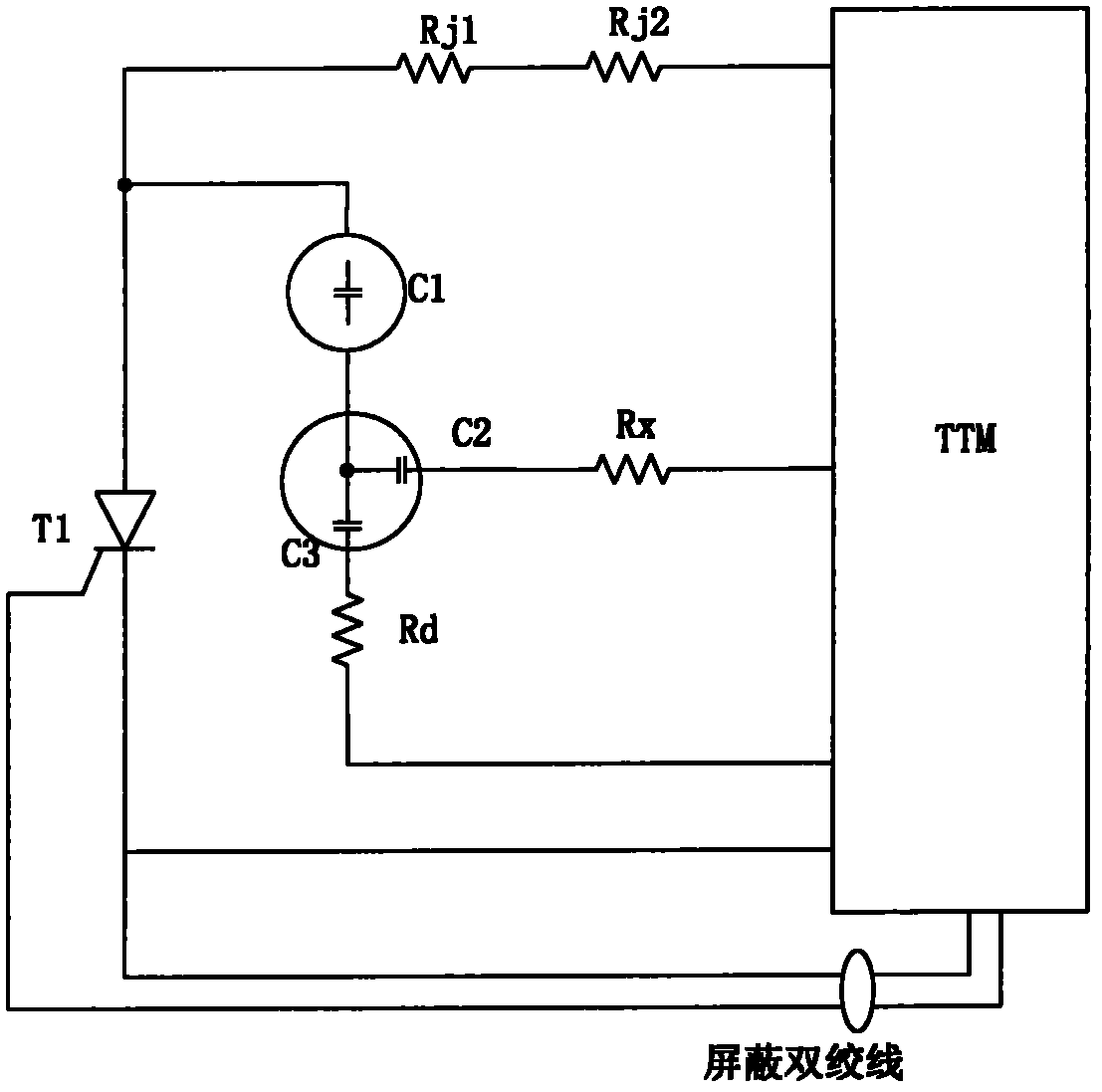
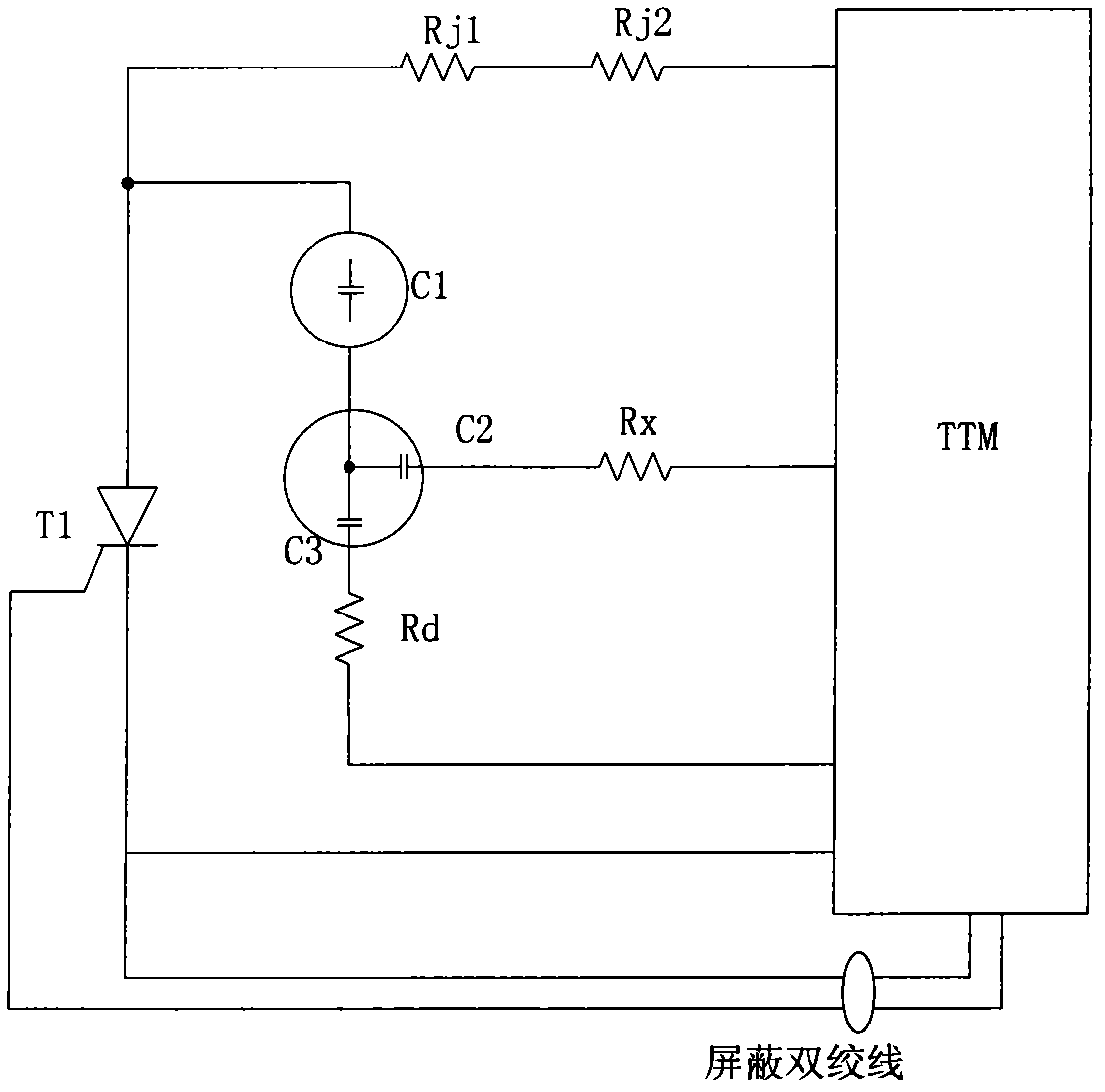
[0012] The electrical structure of the thyristor-level damping circuit of the converter valve designed in the present invention is as attached figure 1 shown.

[0013] attached figure 1 Among them, T1 is a thyristor, the anode of the thyristor is connected to the damping capacitor C1 and TTM, the cathode and gate of the thyristor are connected to the thyristor triggering and monitoring unit TTM, the anode and cathode of the thyristor are connected to the TTM, and the TTM is introduced in the circuit design The voltage of the thyristor is divided to convert the high voltage of the anode and cathode of the thyristor into a voltage range that can make the circuit board work normally.

[0014] The damping circuit of the DC converter valve is composed of DC voltage equalizing resistors Rj1, Rj2, damping capacitors C1, C2, C3, damping resistor Rd, and fast energy-taking resistor Rx. connect. Capacitors C2 and C3 are connected in parallel, and after being connected in parallel, th...


PUM


Abstract

The invention discloses a design of a novel direct-current converter valve thyristor damping loop, which can meet all requirements on electrical designs. The damping loop consists of a direct-current voltage-equalizing resistor, a damping resistor and a damping capacitor, wherein the direct-current voltage-equalizing resistor plays a role in equalizing the voltage of a converter valve and provides a loop for voltage detection of a circuit board. The damping capacitor consists of three capacitors, wherein one damping capacitor plays a role in dividing a voltage; one damping capacitor and the damping resistor are connected in series to form a damping loop; and another damping capacitor is connected in series with a quick energy-taking loop resistor to form a quick energy-taking loop of a thyristor testing and monitoring (TTM) unit. By the novel design method, the design of the direct-current converter valve thyristor damping loop is simplified as possible in the situation of meeting requirements.

Description

technical field [0001] The invention relates to the field of power electronic devices, in particular to a novel thyristor damping circuit of a DC converter valve. Background technique [0002] The thyristor damping circuit is an important part of the thyristor-level circuit. Most of the modern design ideas are composed of RC circuits to form the damping circuit. The damping circuit designed by this invention is shown in the appendix figure 1 shown. During the normal operation of the converter valve, since the converter valve is composed of multiple thyristors in series, the thyristors of each stage should bear a similar voltage, and the damping circuit plays the role of internal dynamic pressure equalization. In addition, The damping circuit provides an energy harvesting circuit for the thyristor trigger and monitoring unit TTM. TTM is a thyristor-level triggering, monitoring and protection device. The voltage and current reach the required value, so it can ensure its norm...

Claims


Application Information

Patent Timeline
Patent Type & Authority Applications(China)
IPC IPC(8): H02M1/06H02M1/32
Inventor 汤广福陈龙龙王华锋
Owner CHINA ELECTRIC POWER RES INST
Why Eureka
Try Eureka