
Ultrasonic vibration auxiliary grinding method of ultrahard linear microstructural surface

A technology of ultrasonic vibration and microstructure, which is applied in the field of ultrasonic vibration-assisted grinding, can solve the problems of destroying microstructure surface surface accuracy, etc., and achieve the effects of reducing broken phenomena, improving surface quality and avoiding interference

Inactive Publication Date: 2013-03-20
HARBIN INST OF TECH +1
View PDF0 Cites 0 Cited by
  • Summary
  • Abstract
  • Description
  • Claims
  • Application Information

AI Technical Summary

Problems solved by technology

[0006] In order to solve the problem that the vibration trajectory will interfere with the microstructure surface structure when the microstructure surface is processed by the existing ultrasonic vibration assisted grinding method, thereby destroying the surface accuracy of the microstructure surface, the invention further provides a superhard linear Ultrasonic Vibration Assisted Grinding Method for Microstructured Surfaces

Method used


Image

  • Ultrasonic vibration auxiliary grinding method of ultrahard linear microstructural surface
  • Ultrasonic vibration auxiliary grinding method of ultrahard linear microstructural surface

Examples


specific Embodiment approach 1

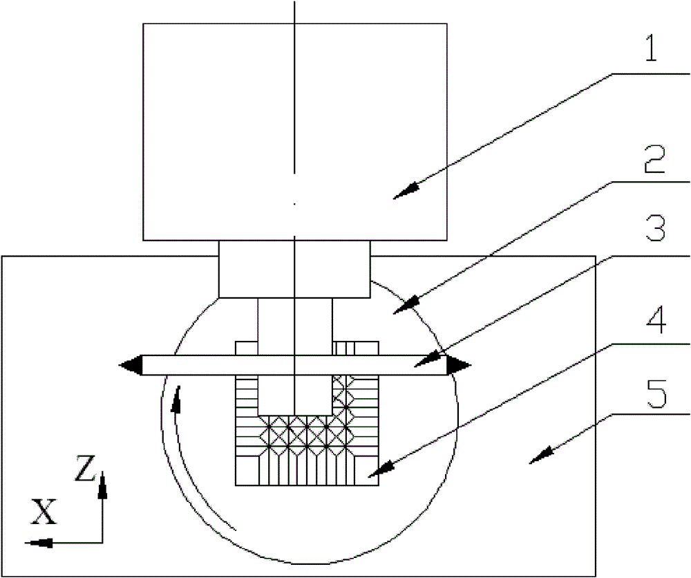
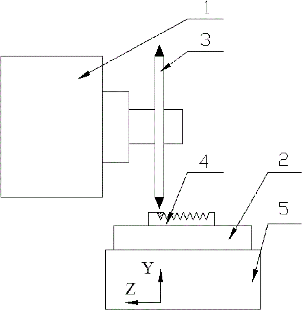
[0014] Specific implementation mode one: combine Figure 1~2 Note that the ultrasonic vibration-assisted grinding method described in this embodiment is implemented according to the following steps:

[0015] Step 1. Install the diamond profiling grinding wheel 3 on the spindle 1 of the plane precision grinding machine tool, install the ultrasonic vibration table 2 on the precision grinding machine table 5, and fix the workpiece 4 to be ground on the upper end surface of the vibration table 2 at the center of

[0016] Step 2. Apply one-dimensional ultrasonic vibration to the vibrating table through the ultrasonic generator, and at the same time drive the workpiece to be ground on the vibrating table to perform one-dimensional ultrasonic vibration. When grinding the parallel linear microstructure surface, that is, the V-shaped groove matrix surface Or the grating microstructure surface, use the rotating table to adjust the vibration direction of the one-dimensional ultrasonic v...

specific Embodiment approach 2

[0018] Specific embodiment two: the rotational speed of the grinding wheel in step two of this embodiment is 3000 rpm. When the grinding wheel speed is 3000rpm, the processing effect is the best, and the surface quality after processing is the highest. Other compositions and connections are the same as those in Embodiment 1.

specific Embodiment approach 3

[0019] Embodiment 3: The ultrasonic vibration amplitude in step 2 of this embodiment is 5 μm. When the amplitude is 5 μm, the vibration effect is the best, and the surface quality after processing is the highest. Other compositions and connections are the same as those in the first or second embodiment.


PUM


Abstract

The invention discloses an ultrasonic vibration auxiliary grinding method of an ultrahard linear microstructural surface, which relates to an ultrasonic vibration auxiliary grinding method, and is used for solving the problem that the surface flatness on the microstructural surface is damaged caused by the reason that the vibration track is interfered with the microstructural surface structure when the microstructural surface is processed by the existing ultrasonic vibration auxiliary grinding method. The method comprises the following steps: applying one-dimensional ultrasonic vibration to a vibration working table by an ultrasonic generator; when a parallel linear microstructural surface, namely a V-shaped groove matrix surface or a grating microstructural surface is ground, adjusting the vibration direction of the one-dimensional ultrasonic vibration table to be parallel to a grinding wheel feeding direction by utilizing a rotary platform; controlling the grinding wheel cutting direction to be opposite to the grinding wheel feeding direction; controlling the ultrasonic vibration frequency of the ultrasonic generator to be 25-35KHz, the ultrasonic vibration amplitude to be 1-10 mu m, the grinding wheel rotary speed to be 2000-4000rpm, and the workpiece feeding speed to be 0.2-2mm / min. The method provided by the invention is used for precisely processing the ultrahard microstructural surface.

Description

technical field [0001] The invention relates to an ultrasonic vibration assisted grinding method, in particular to an ultrasonic vibration assisted grinding method for a linear microstructure surface. Background technique [0002] Optical functional components with microstructured surfaces are key components in the manufacture of micro-optoelectronic systems. They have the advantages of light weight and miniaturization of the system, and can realize new functions such as miniaturization, array, integration and wavefront conversion that are difficult to achieve with ordinary optical components. . [0003] Optical functional components with microstructured surfaces are usually manufactured using replica processing technology, where the precision machining quality of superhard material molds with microstructured surfaces (such as binder-free tungsten carbide, CVD silicon carbide, and HIP silicon carbide) has a great impact on final product performance and cost. Control plays a...

Claims


Application Information

Patent Timeline
Patent Type & Authority Patents(China)
IPC IPC(8): B24B1/04
Inventor 梁迎春郭兵吴晓健赵清亮赵玲玲王义龙孙国燕
Owner HARBIN INST OF TECH
Learn More