
Aluminum electrolysis anode device and preparation method thereof

A technology of aluminum electrolysis anodes and anode steel claws, which is applied in the manufacture of tools and ceramic molding machines, etc., can solve the problems of shortening the service life of aluminum electrolysis anode devices, damage to the health of operators, and polluting the atmospheric environment. Energy saving and low energy consumption

Inactive Publication Date: 2011-08-31
ZIBO CHUNGENG IND & TRADE
View PDF3 Cites 3 Cited by
  • Summary
  • Abstract
  • Description
  • Claims
  • Application Information

AI Technical Summary

Problems solved by technology

The shortcomings of this structure and production method are: phosphorus pig iron needs to be heated to above 130°C when melting, which consumes a lot of power, and a large amount of harmful gases such as carbon dioxide are produced during the melting process of phosphorus pig iron, which seriously pollutes the air environment , especially the high concentration of harmful gases in the operation workshop, which will cause great damage to the health of the operators; in addition, when the aluminum electrolysis anode device is produced in aluminum electrolysis, when the level of anodic oxidation and electrolysis rises, it is easy to cause phosphorus pig iron Being washed away and melted away, the quality of the primary aluminum is reduced, and the service life of the aluminum electrolysis anode device is shortened; since the phosphorus pig iron is in contact with the anode carbon block, it is fully contacted by the thermal expansion of the phosphorus pig iron, and their contact pressure drop is relatively high , resulting in higher power consumption during electrolysis, etc.

Method used


Image

  • Aluminum electrolysis anode device and preparation method thereof
  • Aluminum electrolysis anode device and preparation method thereof

Examples


Embodiment Construction

[0013] The present invention will be further described with reference to the accompanying drawings and examples.

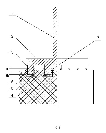
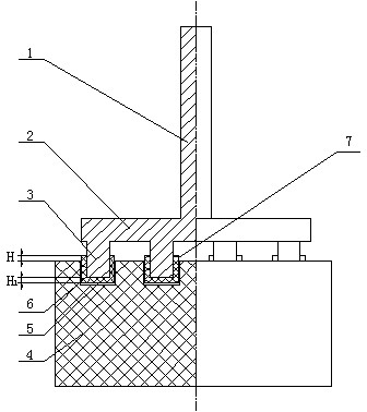
[0014] The present invention reaches the advantages described in the present invention in order to accomplish the object of the invention, and the embodiment in the technical scheme that provides is: as figure 1 As shown, 4 in the figure is an anode carbon block, a carbon bowl 5 is provided on the top of the anode carbon block 4, and the anode steel claw 3 is placed in the carbon bowl 5, and the cavity between the carbon bowl 5 and the anode steel claw 3 is filled with carbon material 6 , The weight ratio of raw materials used in the carbon material 6 is: artificial graphite 45-80, metal shavings 5-40 and resin binder 15-20. The preferred weight ratio of raw materials used in the carbon material 6 of the present invention is: artificial graphite 55-75, metal scrap 10-30 and resin binder 15-20. The resin binder can be powder, liquid or semi-dry powder. Resin bind...


PUM

PropertyMeasurementUnit
thicknessaaaaaaaaaa
specific surface areaaaaaaaaaaa

Abstract

The invention discloses an aluminum electrolysis anode device and a preparation method thereof. The aluminum electrolysis anode device comprises an anode carbon block, wherein the upper part of the anode carbon block is provided with a carbon bowl, an anode steel claw is arranged in the carbon bowl, and a cavity between the carbon bowl and the anode steel claw is filled with a carbon material; and the carbon material is prepared from the following raw materials in parts by weight: 45-80 parts of artificial graphite, 5-40 parts of scrap metal and 15-20 parts of resin binder. The preparation method comprises the following steps: (1) taking the processed anode carbon block and anode steel claw for later use; (2) taking the raw materials in parts by weight, and evenly mixing to obtain the carbon material; (3) compacting the carbon material; (4) putting the anode steel claw into the carbon bowl, so that the center of the anode steel claw coincides with the center of the carbon bowl; and (5) solidifying the carbon material at normal temperature or under heating conditions. The invention does not use the phosphorus pig iron or anode carbon block, and the connection mode thereof, thereby overcoming the defects in the publicly-known technology.

Description

technical field [0001] The invention relates to equipment used in aluminum electrolysis production, and is an aluminum electrolysis anode device and a preparation method thereof. Background technique [0002] The aluminum electrolytic anode device (also known as anode carbon block group) used in aluminum electrolysis production is composed of anode carbon block, anode guide rod and anode steel claw. Usually the anode guide rod and the anode steel claw are integrated, and the anode steel claw and the anode carbon block are melted, cast and cooled with phosphorus pig iron and then connected as a whole. The shortcomings of this structure and production method are: phosphorus pig iron needs to be heated to above 130°C when melting, which consumes a lot of power, and a large amount of harmful gases such as carbon dioxide are produced during the melting process of phosphorus pig iron, which seriously pollutes the air environment , especially the concentration of harmful gases in ...

Claims


Application Information

Patent Timeline
Patent Type & Authority Applications(China)
IPC IPC(8): C25C3/12B28B1/00B28B3/00
Inventor 朱振国谭春耕谭春雷
Owner ZIBO CHUNGENG IND & TRADE
Learn More