
Fuel cell, electronic device and buffer solution for fuel cell

A technology of fuel cells and buffer substances, which is applied to fuel cell components, fuel cells, biochemical fuel cells, etc., and can solve problems such as insufficient energy conversion efficiency

Inactive Publication Date: 2011-08-31
SONY CORP
View PDF12 Cites 5 Cited by
  • Summary
  • Abstract
  • Description
  • Claims
  • Application Information

AI Technical Summary

Problems solved by technology

Therefore, in the aforementioned methods, electrical energy is consumed by undesired reactions, thus not exhibiting sufficient energy conversion efficiency

Method used


Image

  • Fuel cell, electronic device and buffer solution for fuel cell
  • Fuel cell, electronic device and buffer solution for fuel cell
  • Fuel cell, electronic device and buffer solution for fuel cell

Examples


no. 1 approach

[0105]1. First Embodiment (Biofuel Cell)

[0106] 2. Second Embodiment (Biofuel Cell)

no. 3 approach

[0107] 3. Third Embodiment (Biofuel Cell and Manufacturing Method Thereof)

[0108] 4. Fourth Embodiment (Biofuel Cell)

[0109] 5. Fifth Embodiment (Biofuel Cell)

[0110] 6. Sixth embodiment (biofuel cell)

[0111] 7. Seventh Embodiment (Biofuel Cell)

[0112]

[0113] [Biofuel cell]

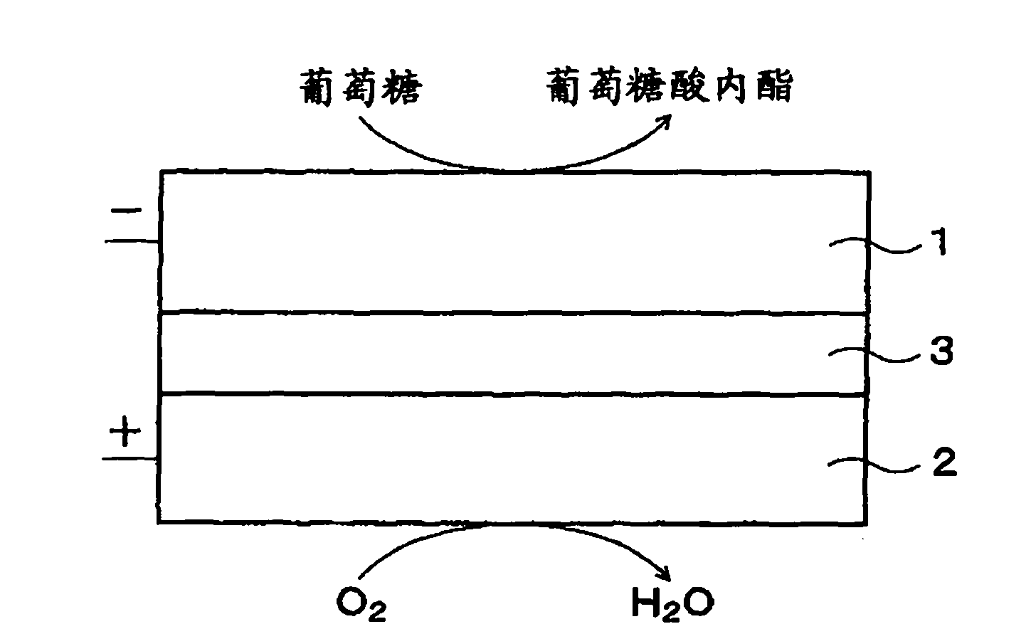
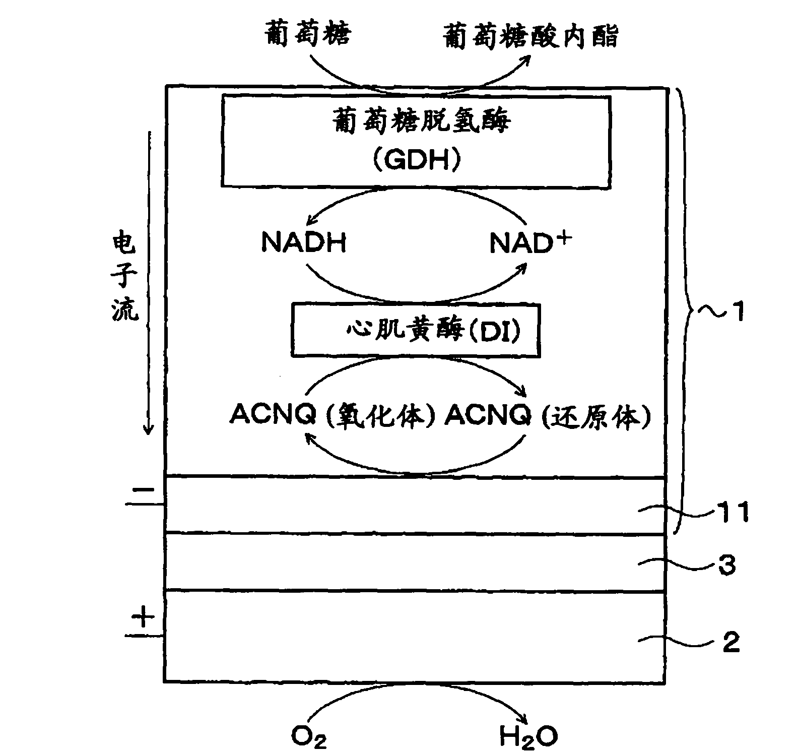
[0114] figure 1 A biofuel cell according to a first embodiment of the present invention is schematically shown. In the biofuel cell, glucose is used as fuel. figure 2 The structure of the negative electrode of the biofuel cell, an example of an enzyme group immobilized to the negative electrode, and details of electron transfer and reception reactions by the enzyme group are schematically shown.

[0115] The biofuel cell has a structure in which a negative electrode 1 and a positive electrode 2 are arranged opposite to each other with an electrolyte layer 3 in between. In the negative electrode 1, glucose supplied as fuel is degraded by enzymes, electrons are extracted, and protons (...

no. 2 approach

[0165] [Biofuel cell]

[0166] Next, a description will be given of a biofuel cell according to a second embodiment of the present invention.

[0167] In the biofuel cell, the electrolyte layer 3 has a charge of the same sign as that of an oxidant or a reducer of an electron mediator for the positive electrode 2 and the negative electrode 1 . For example, at least the surface of the electrolyte layer 3 on the positive electrode 2 side is negatively charged and has a negative charge. In particular, for example, polyanions having a negative charge are contained in all or a part of at least the portion on the positive electrode 2 side of the electrolyte layer 3 . Suitably, as the polyanion, Nafion (product name, manufactured by DuPont USA) is used as an ion exchange resin having a fluorine-containing sulfonic acid group.

[0168] A description will be given of the results of a comparative experiment conducted to verify that the oxidized or reduced body of the electron mediator ...


PUM

PropertyMeasurementUnit
Viscosityaaaaaaaaaa
Conductivityaaaaaaaaaa

Abstract

Provided is a fuel cell having an excellent performance, wherein sufficient buffering power can be obtained during high output operation when an enzyme is immobilized on a positive electrode and / or a negative electrode, and the enzyme can exert intrinsic abilities thereof sufficiently. Specifically disclosed is a biofuel cell having a structure wherein a positive electrode 2 and a negative electrode 1 are arranged opposite to each other with an electrolyte layer 3 containing a buffering substance interposed therebetween, and an enzyme is immobilized on the positive electrode 2 and / or the negative electrode 1. The electrolyte layer 3 contains, as a buffering substance, a compound having an imidazole ring, and at least one acid selected from the group consisting of acetic acid, phosphoric acid and sulfuric acid is added thereto. Imidazole, 1-methylimidazole, 2-methylimidazole, 4-methylimidazole, 2-ethylimidazole or the like is used as the compound having an imidazole ring.

Description

technical field [0001] The present invention relates to a fuel cell in which an enzyme is immobilized to one or both of a positive electrode and a negative electrode, an electronic device using the fuel cell, and a fuel cell buffer solution suitable for the fuel cell. Background technique [0002] A fuel cell has a structure in which a positive electrode (oxidant electrode) and a negative electrode (fuel electrode) are arranged facing each other with an electrolyte (proton conductor) interposed therebetween. In existing fuel cells, fuel (hydrogen) is supplied to the negative electrode to be oxidized and separated into electrons and protons (H + ). Electrons are transported to the negative electrode, H + Move to the positive electrode through the electrolyte. In the positive electrode, these H + Reacts with oxygen supplied from the outside and electrons sent from the negative electrode through an external circuit to generate H 2 O. [0003] As described above, a fuel ce...

Claims


Application Information

Patent Timeline
IPC IPC(8): H01M8/02H01M4/90H01M8/16
CPCH01M2300/0005H01M2300/0088H01M8/16H01M8/086Y02E60/527Y02E60/50C12Q1/26H01M4/90H01M8/02
Inventor 汲田英之三田洋树后藤义夫中川贵晶酒井秀树松本隆平户木田裕一
Owner SONY CORP
Learn More