
Peening hammer and peening hammer component

A technology for striking a hammer and a hammer handle, which is applied in the direction of printing, etc., can solve the problems of affecting the character recognition effect, uneven striking force, incomplete characters, etc., and achieves the effect of good overall structure, excellent structure, and clear and complete printing and writing.

Active Publication Date: 2011-09-07
PRINT RITE UNICORN IMAGE PROD CO LTD
View PDF11 Cites 0 Cited by
  • Summary
  • Abstract
  • Description
  • Claims
  • Application Information

AI Technical Summary

Problems solved by technology

[0013] The impact hammers used in the above two types of impact printers for check printing are cumbersome to produce, and require secondary grinding after each injection molding is completed.
Moreover, even if the hitting surface becomes flat after grinding, the deformation of other parts of the hammer due to uneven wall thickness remains unchanged, which will still lead to uneven hitting strength, and the printed characters will be incomplete, affecting character recognition effect

Method used


Image

  • Peening hammer and peening hammer component
  • Peening hammer and peening hammer component
  • Peening hammer and peening hammer component

Examples


Embodiment 1

[0054] see Figure 15 , 16 And 17, a kind of percussion hammer that is used to be installed on a kind of impact printer, has a sleeve part 21 that is used to be sleeved on the drive shaft and a striking part 22 that is used to beat the dial, the sleeve part 21 and the beating part 22 are integrally formed by injection molding. The sleeve portion 21 has a cylindrical shape, preferably a cylindrical shape in this embodiment, and has an inner diameter consistent with the outer diameter of the drive shaft. And there is a notch on the circumference of the sleeve part 21 which is one-third of the circumference, so that the sleeve part 21 can be fitted onto the drive shaft from the side of the drive shaft in a direction perpendicular to the axis of the drive shaft. In addition, a notch 211 is provided on the outer peripheral surface of the thicker inner diameter section of the sleeve portion 21 to facilitate the operation of the overall manufacturing process of the hammer. The bea...

Embodiment 2

[0057] see Figure 18 , 19 , 20, 21, a hammer used to be installed on another printer has a hammer head 32 and a hammer handle 31. The hammer head 32 is a cylindrical body, which is preferably a cylindrical body in this embodiment. One circular end surface of the cylindrical body is the hitting surface 320, and the center position of the other circular end surface has a cylindrical hole along the axial direction of the cylindrical body. A cylindrical metal body 321 with the same size as the cylindrical hole is inserted into the hole. The end surface area of ​​the cylindrical metal body 321 is larger than the effective striking area of ​​the striking surface 320 . The hammer handle 31 is a long strip with a certain radian, one end of the hammer handle 31 is fixedly connected to the peripheral surface of the hammer head 32, and the other end of the hammer handle 31 is provided with a mounting column 33, which is used to place the hammer Installed on the positioning frame, the...


PUM


Abstract

The invention provides a peening hammer, which comprises a body. One end of the body is provided with a cylindrical driving shaft sleeve part, while the other end is provided with a columnar beating part; the outer end face of the beating part is a beating surface; and the center of the beating part facing the inner end face of the driving shaft sleeve part is provided with a columnar hole along the axis of the column. The peening hammer with the structure has uniform integral wall thickness, cannot shrink or deform in the injection molding process, and has a good structure and flat beating surface. Moreover, a columnar metal body inserted into the columnar hole can indirectly transmit the dynamic of a driving shaft to the beating part of the peening hammer; because the metal body is firmand hard to deform, the contact area of the metal body and the beating part is large, and the metal body and the beating part are firmly contacted, the beating part is uniformly stressed, and the service life of the peening hammer is prevented from being influenced due to severe local abrasion of the peening hammer. In addition, a peening hammer of another printer is correspondingly improved, andthe manufacturing efficiency and product quality of the peening hammer are improved.

Description

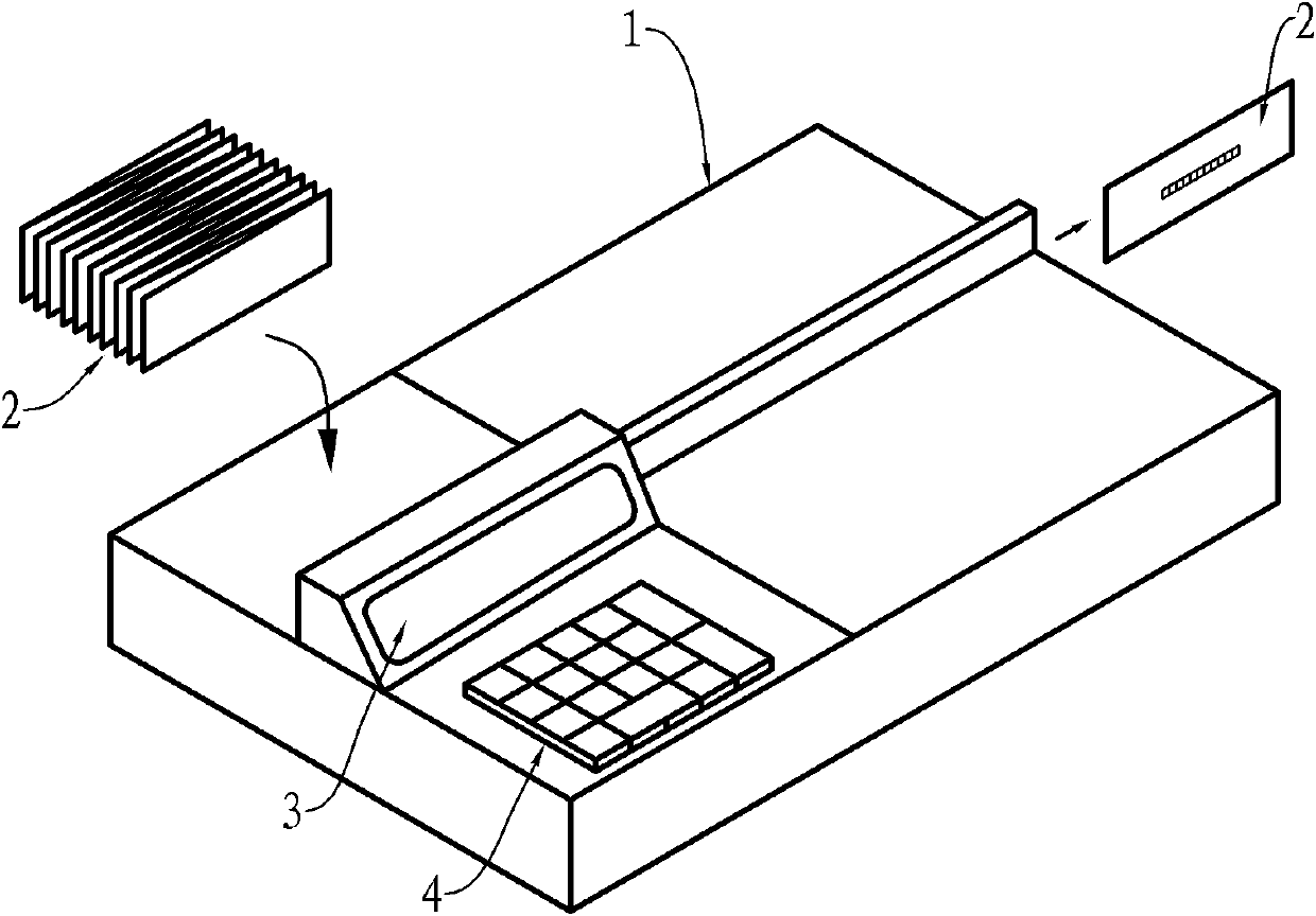
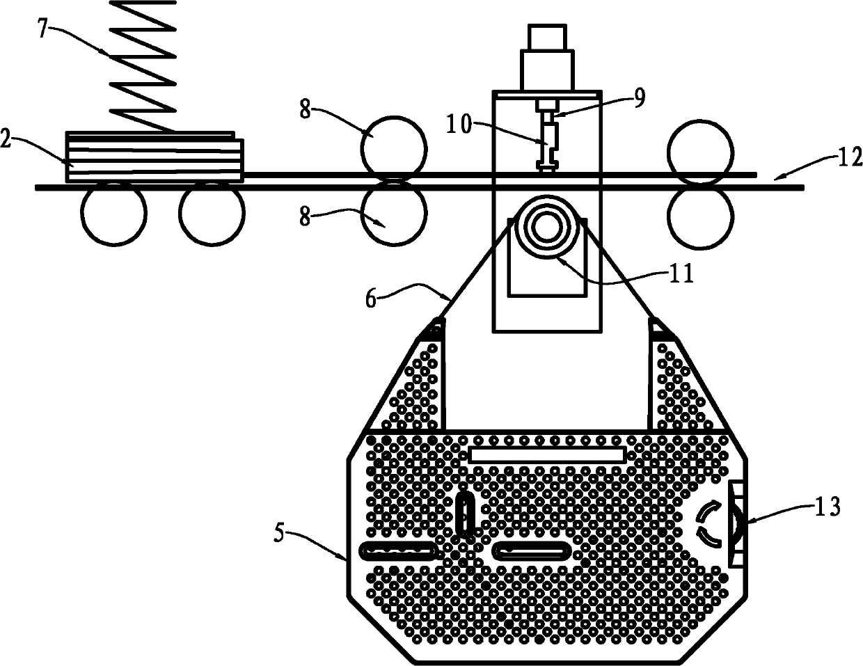
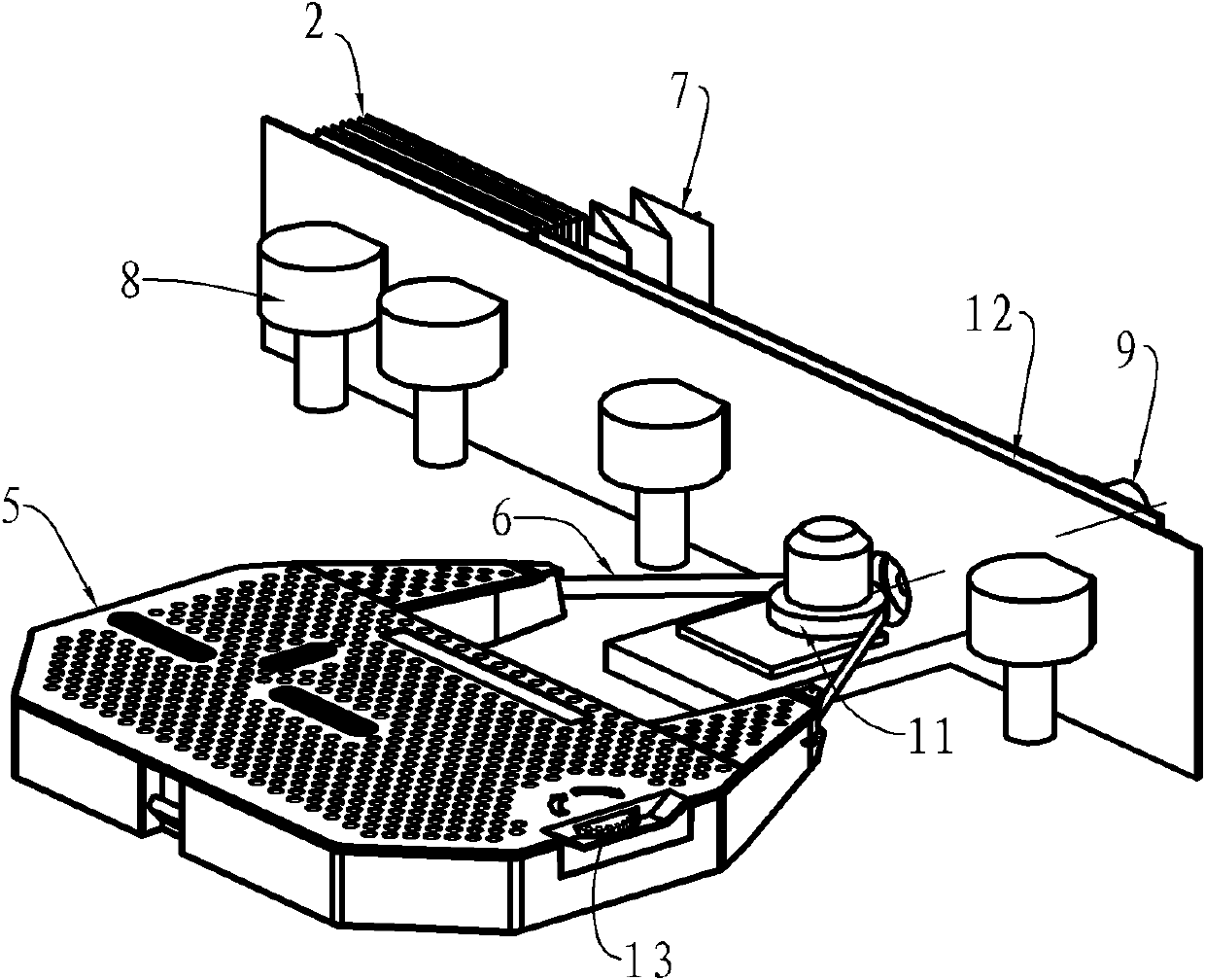
technical field [0001] The invention relates to a printing consumable, especially an impact hammer used in an impact printer, and an impact hammer assembly. Background technique [0002] In the banking system or financial market, an impact printer is usually used to print the amount on a check. It hits the dial through the hammer in the printer, and transfers the toner on the carbon ribbon passing between the hammer and the dial to the printing medium. (that is, checks) for printing purposes. The printed check has low error rate and good anti-counterfeiting performance, and can avoid economic loss. [0003] In the transfer system, checks need to be identified by sorting machines and processed uniformly. Therefore, bank checks must have high recognizability, and the integrity and clarity of their handwriting should be higher than that of ordinary-purpose printed handwriting. The use of magnetic ribbon can make the printing clear and complete. The magnetic carbon ribbon is ...

Claims


Application Information

Patent Timeline
Patent Type & Authority Applications(China)
IPC IPC(8): B41J2/225
Inventor 韦孟站李向福
Owner PRINT RITE UNICORN IMAGE PROD CO LTD
Learn More