Differential transformer type line displacement sensor and manufacture and use methods thereof

A linear displacement sensor and differential transformer type technology, applied in the field of displacement sensors, can solve the problems of error, the inability to detect the output signal, and the inability to realize the miniaturization of the differential transformer type linear displacement sensor, so as to improve the accuracy and linearity, The effect of reducing measurement errors

Inactive Publication Date: 2011-09-07
西安旭彤电子科技股份有限公司
View PDF3 Cites 18 Cited by
  • Summary
  • Abstract
  • Description
  • Claims
  • Application Information

AI Technical Summary

Problems solved by technology

That is, if the linear range of the linear displacement is 10cm, the mechanical stroke must not be less than 20cm. In this way, the miniaturization of the differential transformer linear displacement sensor cannot be realized.
[0019] 2) The output signal cannot be detected
The displacement calculated in this way is that the armature moved 85mm to the left, which has a large error with the actual stroke.

Method used


Image

  • Differential transformer type line displacement sensor and manufacture and use methods thereof
  • Differential transformer type line displacement sensor and manufacture and use methods thereof
  • Differential transformer type line displacement sensor and manufacture and use methods thereof

Examples


Embodiment Construction

[0085] In the following, an example will be illustrated by winding a differential transformer type linear displacement sensor with a measuring range of ±40mm, a sensitivity of 0.05, and a linearity of 0.5%.

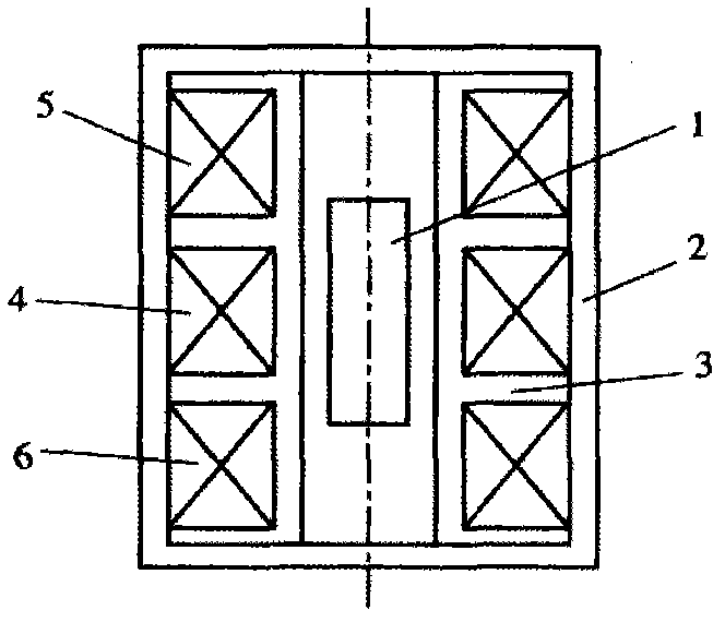
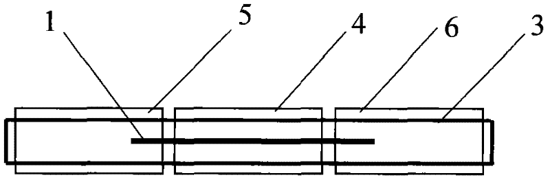
[0086] Such as Image 6 As shown, the differential transformer type linear displacement sensor includes an armature 1 arranged in the center, a skeleton 3 around the armature 1, a primary winding 4 is wound on the skeleton 3, and a secondary winding 1 5 and a secondary winding 2 6 are arranged on the outer layer of the primary winding 4 . Secondary winding 1 5 and secondary winding 2 6 are provided with compensation winding 1 7 and compensation winding 2 8, secondary winding 1 5 and secondary winding 2 6 are out of phase, and compensation winding 1 7 and secondary winding 1 5 are in phase , Compensation winding two 8 and secondary winding two 6 are in phase. Secondary winding 1 5 and secondary winding 2 6 have the same number of turns, and compensation winding 1 7 and c...


PUM


Abstract

The invention relates to a differential transformer type line displacement sensor which comprises an armature, a framework, a primary winding, a secondary winding I and a secondary winding II, wherein a compensation winding I and a compensation winding II are arranged between the secondary winding I and the secondary winding II; phases of the secondary winding I and the secondary winding II are opposite, phases of the compensation winding I and the secondary winding I are same, phases of the compensation winding II and the secondary winding II are same, the tail end of the secondary winding I is connected with the tail end of the compensation winding II, the starting end of the secondary winding II is connected with the tail end of the compensation winding I, and the starting end of the compensation winding I is connected with the starting end of the compensation winding II to be used as a public end. A manufacture method comprises the steps of processing the framework and the armature, winding, regulating and fixing. Voltages of starting ends of the secondary winding I and the secondary winding II are Va and Vb, whether the sum of Va+Vb is within a specified range is judged through calculation, and whether random failures occurs is judged. The differential transformer type line displacement sensor is miniaturized, and has basically same mechanical stroke and linear range; and by using the method, correctness of output signals are effectively judged.

Description

technical field [0001] The invention relates to the field of displacement sensors, in particular to a differential transformer type linear displacement sensor and a manufacturing and using method thereof. Background technique [0002] Differential transformer type linear displacement sensor such as figure 1 As shown, it mainly includes an armature 1 arranged in the center, a skeleton 3 , a primary winding 4 , a secondary winding 5 , a secondary winding 2 6 and a casing 2 . The coupling between primary winding 4 and secondary winding one 5 and secondary winding two 6 can change with the movement of armature 1, that is, the mutual inductance between windings changes with the measured displacement. The number of primary winding 4 turns is Wi; the number of secondary winding one 5 turns is Wa; the number of secondary winding two 6 turns is Wb. [0003] When the armature 1 moves to the side of the secondary winding 6, the mutual inductance W b increase, W b The winding genera...

Claims


Application Information

Patent Timeline
Patent Type & Authority Applications(China)
IPC IPC(8): G01B7/02H01F21/04H01F29/08
Inventor 梁锋王卫斌韦林杨蕾
Owner 西安旭彤电子科技股份有限公司
Why Eureka
Try Eureka