Injection die for injection and pull-extrusion process and method for preparing resin matrix composite by using same

A technology of injection mold and pultrusion process, which is applied in the field of injection mold and the preparation of resin-based composite materials by using it, which can solve the problems of cumbersome structure of injection mold, reduce the probability of worker's misoperation, expand the application range, and improve the mechanical properties.

Active Publication Date: 2011-09-14
HARBIN FRP INST
View PDF6 Cites 23 Cited by
  • Summary
  • Abstract
  • Description
  • Claims
  • Application Information

AI Technical Summary

Problems solved by technology

[0004] The purpose of the present invention is to solve the problem that the structure of the injection mold used in the existing injection pultrusion process is cumbersome. The invention provides an injection mold for the injection pultrusion process and a method for preparing a resin-based composite material using it

Method used


Image

  • Injection die for injection and pull-extrusion process and method for preparing resin matrix composite by using same
  • Injection die for injection and pull-extrusion process and method for preparing resin matrix composite by using same

Examples


specific Embodiment approach 1

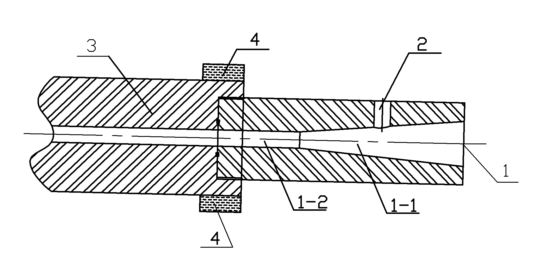
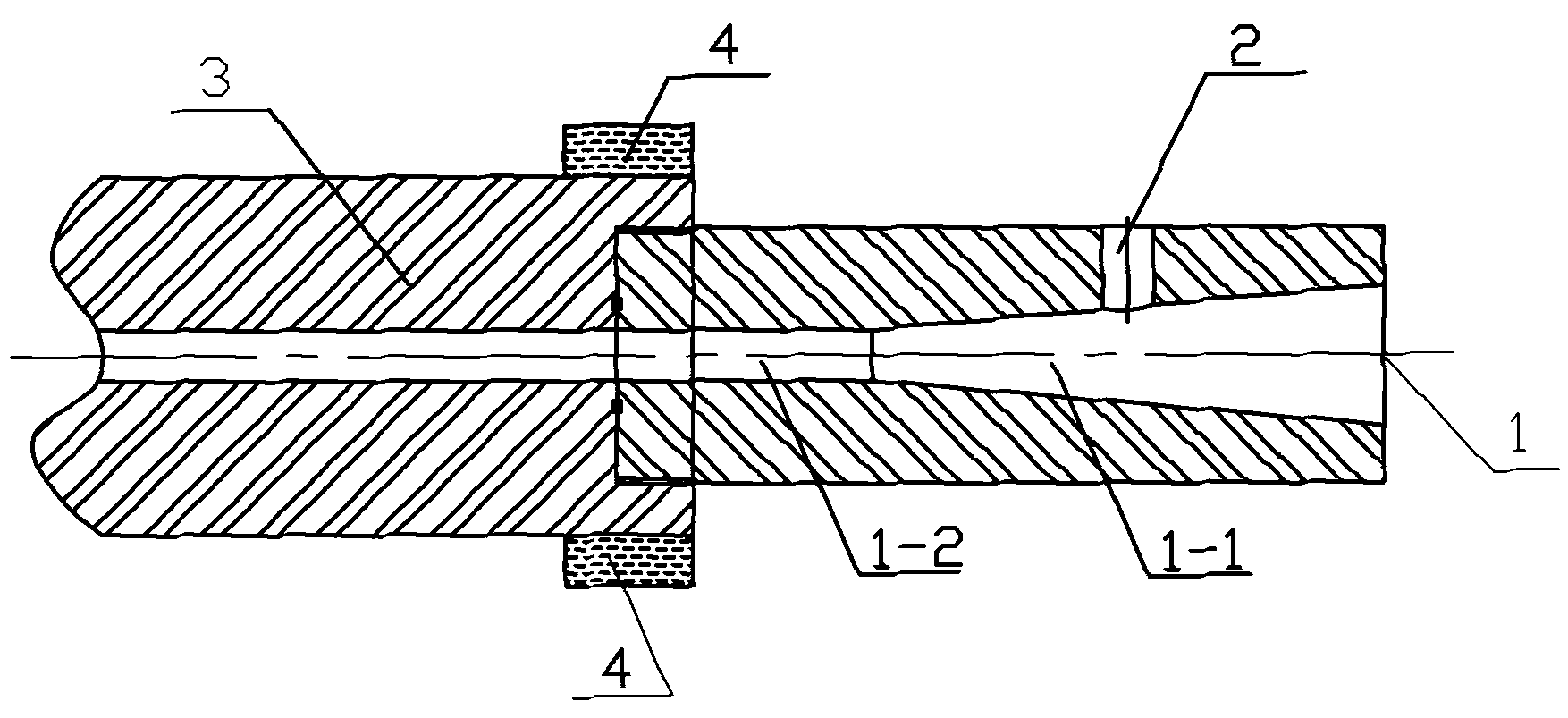
[0019] Specific implementation mode one: combined with figure 1 , indicating that the present embodiment is an injection mold for injection pultrusion process, the injection mold is provided with a mold cavity 1 and a glue injection hole 2, and the mold cavity 1 is composed of a frustum-shaped mold cavity 1-1 and a cylindrical mold cavity 1-2, The glue injection hole 2 is located on the mold wall of the truncated conical mold cavity 1-1, and the glue injection hole 2 is connected with the truncated conical mold cavity 1-1. The small-diameter end of the cavity 1-1 is connected with one end of the cylindrical cavity 1-2, and the diameter of the small-diameter port of the frustum-shaped cavity 1-1 is the same as that of the cylindrical cavity 1-2, and the cylindrical cavity 1 The other end of -2 is in sealing communication with the mold cavity of the pultrusion mold 3, and the outer wall of the injection mold is screwed with the pultrusion mold 3.

[0020] The mold cavity of the...

specific Embodiment approach 2

[0021] Embodiment 2: The difference between this embodiment and Embodiment 1 is that a circulating water cooling device 4 is provided on the outer wall of the pultrusion mold 3 where the outer wall of the injection mold is screwed to the pultrusion mold 3 . Other parameters and connection relations are the same as those in the first embodiment.

[0022] This embodiment is equipped with a circulating water cooling device, which can prevent the resin from solidifying in the injection dipping tooling due to heat transfer due to long-term use.

specific Embodiment approach 3

[0023] Embodiment 3: This embodiment differs from Embodiment 1 or Embodiment 2 in that the number of injection holes 2 is 1 to 4, which are evenly distributed on the mold wall of the truncated conical mold cavity 1-1. Other parameters and connection relations are the same as those in Embodiment 1 or Embodiment 2.

[0024] In this embodiment, the number and position of the injection holes can be adjusted according to the amount of yarn and the viscosity of the resin.


PUM


Abstract

The invention discloses an injection die for an injection and pull-extrusion process and a method for preparing a resin matrix composite by using the same, relating to an injection die and a method for preparing a resin matrix composite by using the same. Through the invention, the problem that the existing injection dies for the injection and pull-extrusion process are complicated in structure is solved. The injection die is provided with a die cavity and a glue injection hole, wherein the die cavity consists of a round table-shaped die cavity and a cylindrical die cavity; and the glue injection hole is located on the die wall of the round table-shaped die cavity. The method comprises the steps of: injecting a resin matrix into the round table-shaped die cavity through the glue injectionhole; causing continuous fibers to enter the die cavity of the injection die from a large-diameter end of the round table-shaped die cavity of the injection die under the traction of a traction device and then enter a die cavity of a pull-extrusion molding die through the cylindrical die cavity; and carrying out sizing and curing. The die cavity of the injection die is conical in front part and flat in rear part, the fibers of a solvent impregnated resin are stressed by a small-diameter end of the round table-shaped die cavity and the die wall of the cylindrical die cavity and then air bubbles are discharged, therefore, the void ratio of the composite is reduced and the mechanical property is improved. The injection die is simplified and the application range of the injection and pull-extrusion process is enlarged.

Description

technical field [0001] The invention relates to an injection mold and a method for preparing resin-based composite materials by using it. Background technique [0002] The pultrusion molding process is one of the main molding processes of composite materials, and its characteristics are: 1. The process is simple and efficient, and is suitable for large-scale production of high-performance fiber composite materials. The pultrusion line speed is known to be above 4m / min, and it can produce multiple products at the same time, which further improves the production efficiency. Second, pultrusion can best play the role of fiber reinforcement. In most composite material manufacturing processes, the fibers are discontinuous, which causes a great loss of fiber strength. Even if continuous fibers are wound, there is a certain loss of strength due to fiber bending and overlapping. For example, in helical winding, the tension of the fiber is generally only 75% to 85%. In pultrusion, ...

Claims


Application Information

Patent Timeline
Patent Type & Authority Applications(China)
IPC IPC(8): B29C70/52
Inventor 王非荆玉玺孙云龙梁钒陈玉廷
Owner HARBIN FRP INST
Why Eureka
Try Eureka