Impermeable choking and grouting method for rock plug truncated cone shell in deepwater
A truncated cone and shell technology is applied in the field of underwater rock plug surrounding rock quality improvement consolidation grouting, seepage prevention and consolidation grouting of underwater cavern blasting surrounding rock mass, can solve problems such as leakage irrigation, and ensure the Safety and reliability, improving rock mass quality, and clear and clear process flow
- Summary
- Abstract
- Description
- Claims
- Application Information
AI Technical Summary
Problems solved by technology
Method used
Image
Examples
Embodiment 1
[0052] Including the following steps:
[0053]1. Drilling layout design
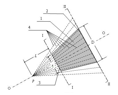
[0054] a) Find a point on the extension line of the axis of rock plug 1 toward the inside of the cave P ,Such as Figure 1a As shown, make the distance between this point and the lower mouth of the rock plug 3 L Satisfies the following formula:
[0055]
[0056] In the formula: —The diameter of the lower opening of the rock plug, in m;
[0057] —The diameter of the upper opening of the rock plug, in m;
[0058] - rock plug thickness coefficient, generally take 1.1;
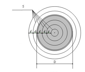
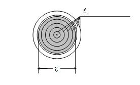
[0059] b) Taking the axis of the rock plug body as the axis, with P The point is the apex of the cone, and each coaxial conical surface 4 and the plane of the lower mouth of the rock plug 3 and the plane of the upper mouth of the rock plug 2 are cut into a lower mouth truncated cone concentric circle 6 and an upper mouth truncated cone concentric circle 5, Figure 1b and Figure 1c shown;
[0060] c) Make the truncated circl...
Embodiment 2
[0088] Including the following steps:
[0089] 1. Drilling layout design
[0090] a) Find a point on the extension line of the axis of rock plug 1 toward the inside of the cave P ,Such as Figure 1a As shown, make the distance between this point and the lower mouth of the rock plug 3 L Satisfies the following formula:
[0091]
[0092] In the formula: —The diameter of the lower opening of the rock plug, in m;
[0093] —The diameter of the upper opening of the rock plug, in m;
[0094] - rock plug thickness coefficient, generally take 1.2;
[0095] b) Taking the axis of the rock plug body as the axis, with P The point is the apex of the cone, and each coaxial conical surface 4 and the plane of the lower mouth of the rock plug 3 and the plane of the upper mouth of the rock plug 2 are cut into a lower mouth truncated cone concentric circle 6 and an upper mouth truncated cone concentric circle 5, Figure 1b and Figure 1c shown;
[0096] c) Make the truncated circ...
Embodiment 3
[0124] Including the following steps:
[0125] 1. Drilling layout design
[0126] a) Find a point on the extension line of the axis of rock plug 1 toward the inside of the cave P ,Such as Figure 1a As shown, make the distance between this point and the lower mouth of the rock plug 3 L Satisfies the following formula:
[0127]
[0128] In the formula: —The diameter of the lower opening of the rock plug, in m;
[0129] —The diameter of the upper opening of the rock plug, in m;
[0130] - rock plug thickness coefficient, generally take 1.4;
[0131] b) Taking the axis of the rock plug body as the axis, with P The point is the apex of the cone, and each coaxial conical surface 4 and the plane of the lower mouth of the rock plug 3 and the plane of the upper mouth of the rock plug 2 are cut into a lower mouth truncated cone concentric circle 6 and an upper mouth truncated cone concentric circle 5, Figure 1b and Figure 1c shown;
[0132] c) Make the truncated circ...
PUM
 Abstract
Description
Claims
Application Information
 - R&D
- Intellectual Property
- Life Sciences
- Materials
- Tech Scout
- Unparalleled Data Quality
- Higher Quality Content
- 60% Fewer Hallucinations
Browse by: Latest US Patents, China's latest patents, Technical Efficacy Thesaurus, Application Domain, Technology Topic, Popular Technical Reports.
© 2025 PatSnap. All rights reserved.Legal|Privacy policy|Modern Slavery Act Transparency Statement|Sitemap|About US| Contact US: help@patsnap.com


