Magnetic suspension horizontal shaft direct-driving type wind driven generator with five freedom degrees

A magnetic levitation bearing and magnetic levitation technology, which is applied to wind turbine components, wind turbines, wind turbines in the same direction as the wind, etc., can solve the problem that the wind turbine cannot achieve all five degrees of freedom suspension, the use and operation of the magnetic suspension bearing system High cost, inability to further reduce the cut-in wind speed, etc., to achieve broad market application prospects, low practical and operating costs, and low noise

Inactive Publication Date: 2011-09-14
NANJING UNIV OF TECH
View PDF3 Cites 15 Cited by
  • Summary
  • Abstract
  • Description
  • Claims
  • Application Information

AI Technical Summary

Problems solved by technology

[0005] In the existing all-permanent-magnet maglev wind turbines, the rotor of the wind turbine cannot be suspended in all five degrees of freedom, so the mechanical friction between the rotating part and the non-rotating part of the fan has not been completely eliminated, and further Reduce cut-in wind speed
[0006] In order to realize the five-degree-of-freedom suspension of the wind turbine rotor, the support system adopted must have active magnetic suspension bearings. If the electromagnetic bias type magnetic suspension bearing is used, it will bring a large energy loss. In addition, If active magnetic bearings are used in multiple degrees of freedom, the scale of the control system will be increased, resulting in higher use and operating costs of the magnetic bearing system

Method used


Image

  • Magnetic suspension horizontal shaft direct-driving type wind driven generator with five freedom degrees
  • Magnetic suspension horizontal shaft direct-driving type wind driven generator with five freedom degrees

Examples


Embodiment Construction

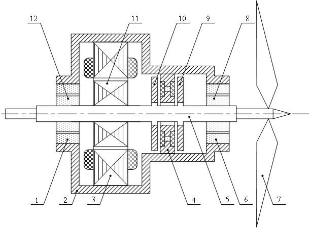
[0015] Such as figure 1 As shown, the permanent magnet type radial magnetic suspension bearing A stator 1, the generator stator 3, the permanent magnetic bias type axial magnetic suspension bearing stator 4, and the permanent magnetic radial magnetic suspension bearing B stator 6 are all fixed inside the housing 2, wherein, The generator stator 3 is located between the permanent magnet radial magnetic suspension bearing A stator 1 and the permanent magnet bias axial magnetic suspension bearing rotor B10, and the permanent magnet bias axial magnetic suspension bearing stator 4 is located between the permanent magnetic bias axial magnetic suspension bearing Between the bearing rotor B10 and the permanent magnet bias type axial magnetic suspension bearing rotor A9.

[0016] Permanent magnetic radial magnetic bearing A rotor 12, generator rotor 11, permanent magnetic bias axial magnetic bearing rotor A9, permanent magnetic bias axial magnetic bearing rotor B10, permanent magnetic ...


PUM

PropertyMeasurementUnit
Widthaaaaaaaaaa

Abstract

A magnetic suspension horizontal shaft wind driven generator with five freedom degrees comprises a stator of a permanent magnet type radial magnetic suspension bearing A at the left end of a shell, a stator of a permanent magnet type radial magnetic suspension bearing B at the right end of the shell, and a stator of a permanent magnet deflection type axial magnetic suspension bearing and a generator stator which are arranged on the inner wall of the shell. A rotor of the permanent magnet type radial magnetic suspension bearing A, a generator rotor, a rotor B of the permanent magnet deflection type axial magnetic suspension bearing, a rotor A of the permanent magnet deflection type axial magnetic suspension bearing, and a rotor of the permanent magnet type radial magnetic suspension bearing B are arranged on a spindle. Two ends of the spindle extend out from two ends of the shell, and fan blades are arranged at one end of the spindle. In the generator, the suspension of the rotors on four radial freedom degrees is realized by the two permanent magnet type radial magnetic suspension bearings, and the suspension of the rotors on an axial freedom degree is realized by the permanent magnet deflection type axial magnetic suspension bearing, so that the full suspension of the rotors is realized, and the cut-in wind speed is reduced, thereby simplifying the structure of a magnetic suspension bearing system of a wind driven generator and enhancing the efficiency of power conversion.

Description

technical field [0001] The invention relates to a horizontal-axis direct-drive wind generator, in particular to a five-degree-of-freedom magnetic levitation horizontal-axis direct-drive wind generator, which belongs to the technical field of wind power generation. Background technique [0002] The principle of wind power generation is to use wind power to drive the generator rotor to rotate to generate electric energy. By comparing different power generation methods, it can be found that wind power generation is green power in a complete sense-no pollution, renewable, and inexhaustible. The global wind energy reserves are huge, about 2.74×10 9 MW. Available wind energy is about 2×10 7 MW, about 10 times the total amount of water energy that can be developed on the earth. my country is rich in wind energy resources, and the wind energy reserves that can be developed and utilized are about 1×10 9 kW, of which, the wind energy storage on land is about 2.53×10 8 kW (at a he...

Claims


Application Information

Patent Timeline
IPC IPC(8): F03D1/00F03D11/00F03D9/25
CPCY02E10/722Y02E10/72
Inventor 张广明梅磊王德明
Owner NANJING UNIV OF TECH
Why Eureka
Try Eureka