Aspherical mirror detection method based on phase measurement deflectometry

An aspheric mirror and detection method technology, which is applied in the detection of aspheric mirrors and the field of optical detection, can solve the problems of high requirements for the environment used, small dynamic range of measurement, and particularly large impact on accuracy, and achieve calculation formulas and calculations. Simple process, large measurement dynamic range, and the effect of suppressing influence

Active Publication Date: 2011-09-14
INST OF OPTICS & ELECTRONICS - CHINESE ACAD OF SCI
View PDF5 Cites 32 Cited by
  • Summary
  • Abstract
  • Description
  • Claims
  • Application Information

AI Technical Summary

Problems solved by technology

However, its measurement dynamic range is very small. When measuring an aspheric surface, it is generally necessary to manufacture auxiliary components. At the same time, it is also very sensitive to mechanical vibration and air disturbance, which has high requirements for the environment in which it is used.
At the same time, in the process of fine grinding, due to its rough surface and large surface error, it is not sui

Method used


Image

  • Aspherical mirror detection method based on phase measurement deflectometry
  • Aspherical mirror detection method based on phase measurement deflectometry
  • Aspherical mirror detection method based on phase measurement deflectometry

Examples


Embodiment Construction

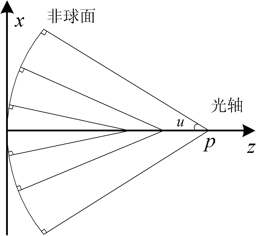
[0021] Such as figure 1 As shown, in fact, any kind of aspheric surface has a normal convergence, and its normal and the optical axis intersect at different points and form different angles, such as figure 1 Shown. The aspheric surface can not only be characterized by its rectangular coordinate system equation, but also by the longitudinal normal aberration and the angle between the normal and the optical axis. For the convenience of description, the present invention refers to the distance between the aspheric surface vertex and the intersection point of the aspheric surface normal and the optical axis as the normal distance, which is represented by p; the inclination of the aspheric surface normal to the optical axis is called the normal angle, Use u to represent. Obviously, in addition to the rectangular coordinate system, the aspheric surface shape can also be characterized by the property of the normal sink, that is, the continuous function g:p=g(u) between the normal dist...


PUM


Abstract

The invention provides an aspheric mirror detection method based on phase measurement deflectometry. The detection system is composed of a display screen, a camera, an electronic control translation stage, a half transparent and half reflecting mirror and an electronic computer, wherein the optical centre of the camera is arranged on the optical axis of the mirror to be detected; a sine (cosine) fringe pattern is generated by the computer and is displayed on the display screen; then the fringe pattern on the display screen can be projected on the mirror to be detected and the camera can shoot the reflected image; during the process of measurement, the mirror to be detected is fixed on the electronic control translation stage and can precisely move along the optical axis under the control of the computer; the fringe pattern shot during the moving process of the mirror to be detected can be analyzed and processed to obtain a phase distribution, then the relationship between the normal line distance and the normal angle of the aspherical surface can be obtained by calculation, namely the surface shape can be described by the normal line congruence of the aspherical surface; and meanwhile, the normal line congruence can be converted to the rectangular coordinate system through geometry calculation for evaluation. The invention has a large dynamic measurement range and provides detection means for the accurate grinding and primary polishing processes of a non-spherical reflector with a larger wavefront variation range during processing.

Description

Technical field [0001] The invention relates to an optical detection technology, in particular to a detection method for aspheric mirrors, and belongs to the technical field of advanced optical manufacturing and detection. Background technique [0002] The so-called aspheric optical element refers to an optical element whose surface shape is determined by multiple high-order equations and the radius of each point on the surface shape is different. Aspheric optical parts can correct aberrations, improve image quality, expand the field of view, and simplify the structure of the optical system and reduce the weight. With the development of optical precision processing and optoelectronics, aspheric surfaces are more and more widely used in various optical systems. Therefore, as aspheric surfaces become more and more widely used, the measurement of aspheric surfaces, especially the high-precision measurement of large-diameter deep aspheric surfaces, has become a hot topic now. For a...

Claims


Application Information

Patent Timeline
IPC IPC(8): G01B11/24
Inventor 赵文川伍凡范斌万勇建
Owner INST OF OPTICS & ELECTRONICS - CHINESE ACAD OF SCI
Why Eureka
Try Eureka