Device and method for vibration measurement and failure analysis of rolling bearing
A fault analysis method, rolling bearing technology, applied in the direction of measuring devices, vibration measurement in solids, mechanical bearing testing, etc., can solve the problems that the actual reliability of products needs to be further improved
- Summary
- Abstract
- Description
- Claims
- Application Information
AI Technical Summary
Problems solved by technology
Method used
Image
Examples
Embodiment 1
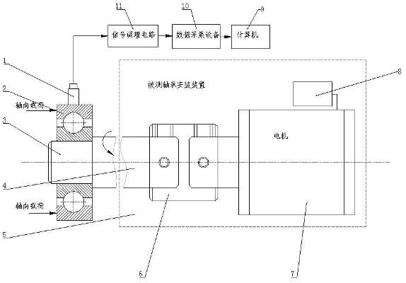
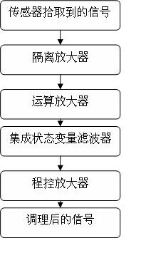
[0027] Embodiment 1: This rolling bearing vibration measurement and fault analysis device, see figure 1 , including a bearing installation device under test (5), a speed sensor (1), a signal conditioning circuit (11), a data acquisition device (10) and a computer (9), characterized in that: firstly, the bearing (2) is installed on the on the bearing mounting device (5). The vibration transmission rod of the speed sensor (1) is placed on the middle plane of the outer cylindrical surface of the bearing outer ring with a specified pressure, and the measurement direction is along the radial direction of the bearing and perpendicular to the axis of the bearing. The radial vibration speed signal of the outer ring of the bearing is measured by the speed sensor (1), and the picked-up radial vibration speed signal of the bearing is converted into a corresponding electrical signal. The electrical signal is sent to the data acquisition device (10) after being processed by the signal con...
Embodiment 2
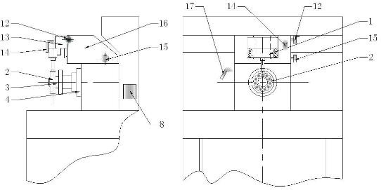
[0028] Embodiment 2: This embodiment is basically the same as Embodiment 1, and the features are as follows: For the tested bearing installation device, see figure 2 , including main shaft (4), motor (7), inverter (8), mandrel (3), vertical slider (13), vertical locking handle (14), hand wheel (12), horizontal slider (16 ), the horizontal locking handle (17), the knob (15), and the bearing (2) and the corresponding mandrel (3) are installed in the taper hole of the main shaft (4). The rotating speed of the main shaft (4) is adjusted by the frequency converter (8), so that the main shaft (4) drives the bearing (2) to rotate at a constant speed. Loosen the vertical locking handle (14) and the horizontal locking handle (17). Adjust the knob (15) to make the horizontal slider (16) move back and forth to complete the adjustment of the horizontal position of the speed sensor (1). Use the hand wheel (12) to raise or lower the vertical slider (13), adjust the vertical position of t...
Embodiment 3
[0030] Embodiment 3: This rolling bearing vibration measurement and failure analysis method uses the above-mentioned device for testing and analysis, see Figure 5 , the data acquisition card starts to work, A / D conversion is performed on the signal conditioned by the signal conditioning circuit, and the data is stored in the user buffer as a voltage value; digital filtering is performed on the collected bearing vibration speed signal to obtain the filtered low frequency Vibration speed signal, medium frequency vibration speed signal and high frequency vibration speed signal; for the filtered bearing vibration speed signal (50-10000hz), respectively calculate the effective value of vibration speed, vibration speed peak value and crest factor of low frequency, medium frequency and high frequency; The filtered bearing vibration velocity signal (50-10000hz) is subjected to time domain analysis, FFT analysis, envelope spectrum analysis, discrete wavelet analysis, wavelet packet ana...
PUM
 Abstract
Description
Claims
Application Information
 - R&D
- Intellectual Property
- Life Sciences
- Materials
- Tech Scout
- Unparalleled Data Quality
- Higher Quality Content
- 60% Fewer Hallucinations
Browse by: Latest US Patents, China's latest patents, Technical Efficacy Thesaurus, Application Domain, Technology Topic, Popular Technical Reports.
© 2025 PatSnap. All rights reserved.Legal|Privacy policy|Modern Slavery Act Transparency Statement|Sitemap|About US| Contact US: help@patsnap.com


