
Method for manufacturing end face of high-power optical fiber laser

A technology of fiber laser and manufacturing method, which is applied in the laser field, can solve problems such as difficult operation and failure to meet requirements, and achieve the effects of high flatness, high finish, and enlarged output area

Inactive Publication Date: 2012-08-22
SHANGHAI BRANCH FUZHOU GAOYI COMM CO LTD
View PDF4 Cites 0 Cited by
  • Summary
  • Abstract
  • Description
  • Claims
  • Application Information

AI Technical Summary

Problems solved by technology

Conventional optical fiber end-face treatment mainly includes stripping, cleaning, cutting and grinding. Because the core of the optical fiber is very thin, the operation is not easy and often fails to meet the requirements

Method used


Image

  • Method for manufacturing end face of high-power optical fiber laser
  • Method for manufacturing end face of high-power optical fiber laser
  • Method for manufacturing end face of high-power optical fiber laser

Examples


Embodiment Construction

[0015] The present invention will be further described below in conjunction with the accompanying drawings and specific embodiments.

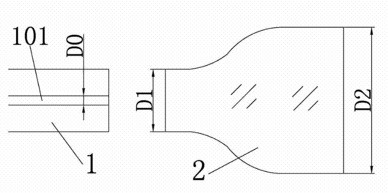
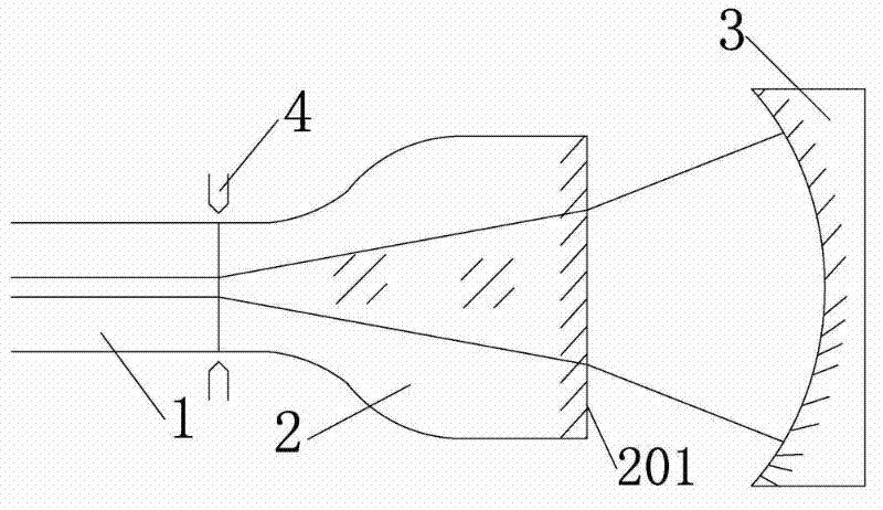
[0016] Such as figure 1 , 2 As shown, the present invention adopts an optical element 2, which is directly melt-connected with the end face of the optical fiber 1 of the high-power fiber laser; the diameter D1 of one end of the optical element 2 is equal to or similar to the diameter of the high-power optical fiber, and the other end is tapered or horn-shaped. The diameter is D2 (D2>D1), and the end surface 201 is coated with an anti-reflection film layer, and forms a laser output end with a plano-concave mirror 3 . Since D2 can be made larger and can be much larger than the diameter D0 of the core 101 of the optical fiber 1, it is easier to handle and obtain high end-face quality.

[0017] The basic principle of a high-power fiber laser end face manufacturing method of the present invention is as follows: figure 1 As shown, it specifically ...


PUM


Abstract

The invention discloses a method for manufacturing the end face of a high-power optical fiber laser. In the method, an optical element which is stretched into a conical element or a trumpet-shaped element is in butt joint with the optical fiber end face of the high-power optical fiber laser. The fiber core diameter of an optical fiber is D0; the diameter of the end of the conical optical element,which is in butt joint with the optical fiber, is D1; the diameter of the other end of the optical element is D2; D1 is more than D0 and less than D2; the end of the optical element, which has the diameter of D1, is integrally molten with the optical fiber in a discharging way; and the end face of the optical element, which has the diameter of D2, is plated with a permeable film and constitutes alaser output end together with a planoconcave lens. The area of the end face with the diameter D2 is large and fine optical processing can be performed conveniently, so that an output end face with high planeness and high smoothness can be obtained.

Description

technical field [0001] The invention relates to the field of lasers, in particular to a method for manufacturing an end face of a high-power fiber laser. Background technique [0002] As a member of solid-state lasers, fiber lasers with all-fiber structure are considered to be the best practical solid-state laser technology due to their simple and compact structure, small size, stable and reliable operation, no need for debugging, good beam quality, and easy integration. choose. Its application range is very wide, including laser optical fiber communication, laser space long-distance communication, industrial shipbuilding, automobile manufacturing, laser engraving, laser marking, laser cutting, printing roller, metal and non-metal drilling / cutting / welding (brazing, quenching , cladding and deep welding), military defense security, medical equipment, large-scale infrastructure, etc. With the expansion of the application range, the power requirements of fiber lasers are gett...

Claims


Application Information

Patent Timeline
Patent Type & Authority Patents(China)
IPC IPC(8): H01S3/067
Inventor 吴砺韩晓明陈燕平
Owner SHANGHAI BRANCH FUZHOU GAOYI COMM CO LTD
Learn More