AC-DC converter with bidirectional energy flow

A two-way flow, converter technology, applied in the field of transformers, can solve the problems of difficulty in implementation and popularization, difficulty in wide application, complex intermediate links, etc., and achieves the effect of good environmental protection, easy productization, promotion and application, and increased efficiency.

Inactive Publication Date: 2011-09-14
SHANGHAI JIAO TONG UNIV
View PDF3 Cites 10 Cited by
  • Summary
  • Abstract
  • Description
  • Claims
  • Application Information

AI Technical Summary

Problems solved by technology

[0003] After searching the existing technical literature, it is found that the Chinese patent application number is: 02139030.4, and the patent name is "Power Electronic Transformer". The power electronic transformer is based on a three-phase-three-phase matrix converter structure, and the intermediate links are very complicated. The difficulty is very high, the economy is low, and it is difficult to realize and promote the application
[0004] The Chinese patent application number is: 200910025824.3, the patent named "Multifunctional Power Electronic Transforme...

Method used


Image

  • AC-DC converter with bidirectional energy flow
  • AC-DC converter with bidirectional energy flow
  • AC-DC converter with bidirectional energy flow

Examples


Embodiment 1

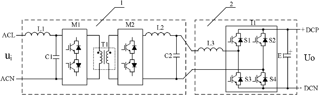
[0026] Such as figure 1 As shown, this embodiment includes: a step-down circuit 1 and a rectification circuit 2 , wherein: the output end of the step-down circuit 1 is connected to the input end of the rectification circuit 2 .

[0027] The step-down circuit 1 includes sequentially cascaded input filters L1, C1, AC chopper circuit M1, AC chopper circuit T1, waveform restoration circuit M2 and output filters L2, C2.

[0028] Both the input filter circuit and the output filter circuit are LC filters.

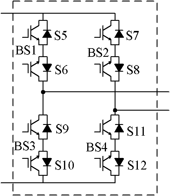
[0029] Such as Figure 2a As shown, the AC chopper circuit M1 is composed of four bridge-connected bidirectional switches BS1, BS2, BS3, and BS4, and each bidirectional switch is composed of two reverse conduction switches connected in series in reverse. Composed of polar transistors and diodes connected in antiparallel. Bidirectional switch BS1 is composed of reverse conduction switches S5 and S6, bidirectional switch BS2 is composed of reverse conduction switches S7 and S8, b...

Embodiment 2

[0039] Such as image 3 As shown, this embodiment relates to a combined AC-DC conversion device, which is composed of three groups of AC-chopped linear AC-DC converters with the same structure, wherein the input of each AC-chopped linear AC-DC converter The terminals are sequentially connected in series, and the output terminals of the three sets of AC chopper linear AC-DC converters are sequentially connected in series and output a DC voltage.

Embodiment 3

[0041] Such as Figure 4As shown, this embodiment relates to a combined AC-DC conversion device, which is composed of three groups of AC-chopped linear AC-DC converters with the same structure, wherein the input of each AC-chopped linear AC-DC converter The terminals are respectively connected to any two phases of the three-phase alternating current, and the output terminals of the three groups of AC chopper linear AC-DC converters are sequentially connected in series and output a direct current voltage.


PUM


Abstract

The invention provides an AC-DC converter with bidirectional energy flow, belonging to the technical field of a transformer. The AC-DC converter comprises a voltage reduction circuit and a rectifier circuit, wherein an output terminal of the voltage reduction circuit is connected with an input terminal of the rectifier circuit; the high-voltage working-frequency alternating-current voltage is converted into the low-voltage working-frequency alternating-current voltage by the voltage reduction circuit; and the low-voltage working-frequency alternating-current voltage is converted into the low-voltage direct-current voltage by the rectifier circuit. The AC-DC converter can realize the conversion between the high-voltage alternating-current voltage and the low-voltage direct-current voltage, has four quadrant capability of an unit input power factor and the bidirectional energy flow, has a simple structure in whole, and enables the whole performance to be more perfect.

Description

technical field [0001] The invention relates to a device in the technical field of transformers, in particular to an AC-DC converter with bidirectional flow of energy. Background technique [0002] Power electronic transformers are mainly composed of power electronic converters, high-frequency transformers and controllers. Including: Insulated gate bipolar transistors or integrated gate commutation gates and other high-frequency and high-power power electronic devices. The power electronic converter is the core of the power electronic transformer, and its function is to complete the frequency and amplitude conversion of electric energy. The function of the high-frequency transformer is isolation and voltage transformation; the function of the controller is to realize the control of power conversion, voltage stability and power quality. [0003] After searching the existing technical literature, it is found that the Chinese patent application number is: 02139030.4, and the p...

Claims


Application Information

Patent Timeline
IPC IPC(8): H02M7/12H02M5/44H02M7/219H02M1/12
CPCH02M5/225H02M7/19H02M7/4807H02M1/0074H02M1/0077
Inventor 马红星李华武蒋婷江剑锋杨喜军
Owner SHANGHAI JIAO TONG UNIV
Why Eureka
Try Eureka