System and method for realizing cogeneration by using heat-conducting oil furnace and semiconductor power generation device

A heat-conducting oil furnace and power generation device technology, which is applied in the direction of generators/motors, heat storage heaters, electrical components, etc., can solve the problems of using a large amount of cooling water, only losing it to the atmosphere, and utilizing the latent heat of cooling liquid vaporization

Inactive Publication Date: 2011-09-14
无锡净利源环保科技有限公司
View PDF5 Cites 15 Cited by
  • Summary
  • Abstract
  • Description
  • Claims
  • Application Information

AI Technical Summary

Problems solved by technology

However, this technology has certain disadvantages: that is, the cooling source of the semiconductor thermoelectric generator needs to use a large amount of cooling water, and the heat taken away by the cooling water can only be recycled after being dissipated by the cooling tower, and the circulation of the cooling water requires a certain amount of electric energy
However, this technology also has problems: since the heat on the cold end surface of the semiconductor thermoelectric power generation module cannot be recycled and can only be lost to the atmosphere, this technology limits the boiling point of the cooling liquid to less than 100°C; inside the evaporator of the cold end surface of the power generat

Method used


Image

  • System and method for realizing cogeneration by using heat-conducting oil furnace and semiconductor power generation device
  • System and method for realizing cogeneration by using heat-conducting oil furnace and semiconductor power generation device
  • System and method for realizing cogeneration by using heat-conducting oil furnace and semiconductor power generation device

Examples


Embodiment Construction

[0020] The present invention will be further described in detail below in conjunction with the drawings and specific embodiments.

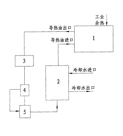
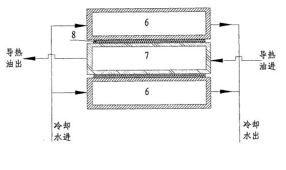
[0021] Such as figure 1 , 2 Shown are the block diagram and structure diagram of the prior art semiconductor thermoelectric generator power generation device, which are marked as: 1-heat exchanger, 2-semiconductor thermoelectric generator, 3-oil storage tank, 4-thermostat, 5- Oil pump, 6-heat conduction oil pipeline, 7-cooling water pipe, 8-semiconductor thermoelectric power generation chip.

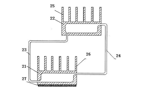
[0022] Such as image 3 Shown is the cooling device used for the semiconductor thermoelectric power generation module, the picture marks: 21-radiator, 22-condenser, 23-pipe, 24-air pipe, 25,26-thin fin, 27-existing Semiconductor thermoelectric power generation module in technology.

[0023] The semiconductor thermoelectric power generation device 50 includes a semiconductor thermoelectric power generation module 68, a power generation module hot end 58, a phase ch...


PUM


Abstract

The invention relates to a system and a method for realizing cogeneration by using a heat-conducting oil furnace and a semiconductor power generation device. The system comprises the heat-conducting oil furnace and a semiconductor temperature difference power generation device connected with the heat-conducting oil furnace through an oil supply pipeline; an oil-gas separator is connected with thesemiconductor temperature difference power generation device through a high temperature heat exchanger; a filter is connected with the heat-conducting oil furnace through a hot oil pump; a standby hot oil pump at the low temperature end is connected with a low temperature heat exchanger; a high-position expansion slot is connected with the oil-gas separator; a low temperature oil storage slot is connected with the oil-gas separator; in a phase-change working medium condenser of a power generation module, an indirect heat exchange mode is adopted, and cold fluid is used as a cooling medium forcooling phase-change working medium steam; and the cold fluid is heated and sent into a subsequent section, so the cogeneration is realized. The invention has the advantages that: high-grade heat energy is recycled and used, and the cogeneration is realized at the same time; moreover, as rotating equipment is absent in the semiconductor temperature difference power generation device, the system is secure and reliable; meanwhile, an aim that heat-conducting oil furnaces at the same temperature supply heat-conducting oil at different temperatures can be fulfilled.

Description

Technical field [0001] The invention relates to a system and method for realizing co-generation of heat and power by using a heat-conducting oil furnace and a semiconductor power generation device. It uses a semiconductor thermoelectric power generation device as a temperature adjustment device to solve the problem of supplying heat-conducting oil at different temperatures while generating power, and can simultaneously produce Steam or hot water is used for heating users, and belongs to the technical field of boiler cogeneration. Background technique [0002] As a special boiler, the heat-conducting oil furnace uses heat-conducting oil as a heat carrier for heating, and is widely used in actual production. Due to the needs of process production and the different heat consumption of various heat equipment, the temperature requirements of the heat transfer oil are also different. Therefore, the heat transfer oil heating station supplies heat transfer oil of different temperatures a...

Claims


Application Information

Patent Timeline
IPC IPC(8): H02N11/00F24H7/02F24H9/12
CPCY02P80/15
Inventor 王海军王海波严红杨勇车红伟
Owner 无锡净利源环保科技有限公司
Why Eureka
Try Eureka