A wet method treatment process of purified flue gas with a water collection function in the process and a processing apparatus thereof

A treatment process and treatment device technology, applied in separation methods, chemical instruments and methods, and dispersed particle separation, etc., can solve problems such as large water consumption, no water recycling or utilization, etc.

Inactive Publication Date: 2011-09-21
王晓晔
View PDF7 Cites 9 Cited by
  • Summary
  • Abstract
  • Description
  • Claims
  • Application Information

AI Technical Summary

Problems solved by technology

[0002] The domestic wet desulfurization technology is relatively mature, but the problem is that the water consumption is relatively large
At present, no matter what kind of wet desulfurization method is used, this part of water is not recovered or utilized

Method used


Image

  • A wet method treatment process of purified flue gas with a water collection function in the process and a processing apparatus thereof
  • A wet method treatment process of purified flue gas with a water collection function in the process and a processing apparatus thereof
  • A wet method treatment process of purified flue gas with a water collection function in the process and a processing apparatus thereof

Examples


Embodiment 1

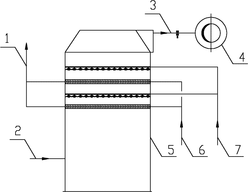
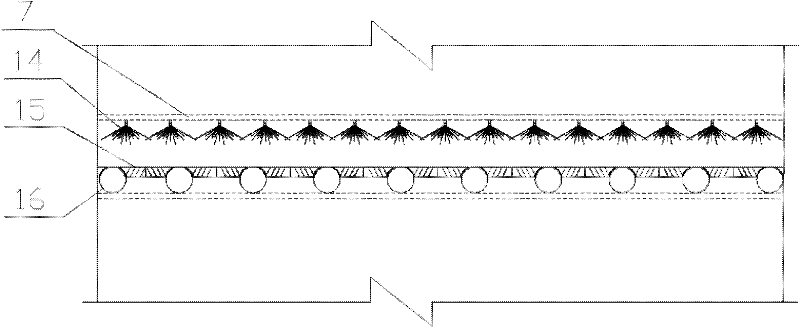
[0028] Such as figure 1 and image 3 As shown, an integrated demister 15 and a cooling device 16 are arranged in the absorption tower 5, and the two ends of the cooling device 16 are respectively connected to the coolant outlet pipe 1 and the coolant inlet pipe 6. In the integrated demister 15 A sprinkler 14 is arranged above the cooling device 16 (that is, a cooler with a demister function), and the sprinkler 14 is connected to the flushing water pipe 7 . The process flow is: the flue gas enters the absorption tower 5 from the original flue 2, and undergoes wet purification in the absorption tower 5, including the water collection function of the demister 15, the cooling device 16 and the water sprayer 14, and then cleans the flue gas It enters the chimney 4 through the clean flue 3 and is discharged.

Embodiment 2

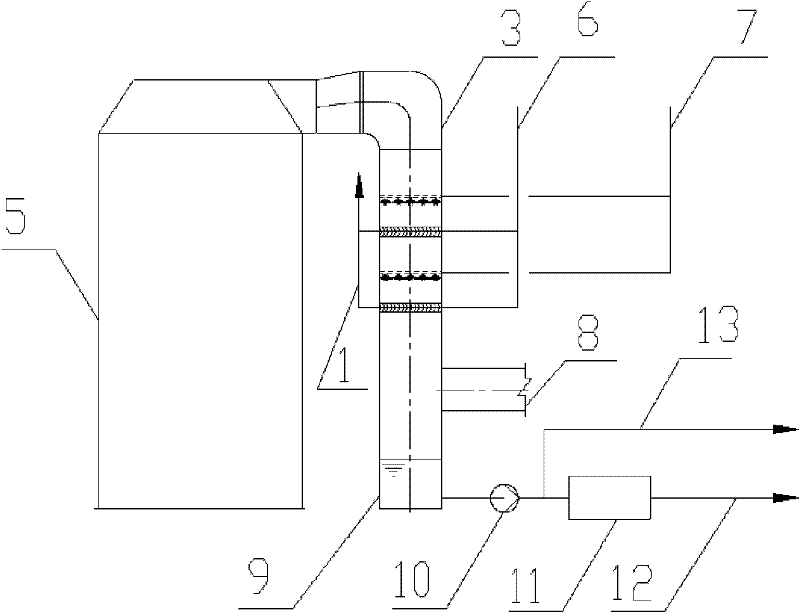
[0030] Such as figure 2 and image 3 As shown, an integrated demister 15 and a cooling device 16 are arranged in the clean flue 3, and the two ends of the cooling device 16 are respectively connected to the coolant outlet pipe 1 and the coolant inlet pipe 6. In the integrated demister 15 and cooling device 16 (that is, the cooler with demister function) is provided with sprinkler 14, and sprinkler 14 is connected to flushing water pipe 7. The clean flue 3 is provided with a clean flue to chimney pipe 8 for discharging clean flue gas, and the clean flue 3 is connected with a recovery water tower 9, and the recovery water tower 9 is connected with a recovery water pump 10, and the recovery water pump 10 is connected with two pipelines, One path is the recycled water pipeline 12 connected to the water treatment device 11 , and the other path is the recycled water desulfurization pipeline 13 . The process flow of this embodiment can be easily understood through the accompanying...


PUM


Abstract

The invention provides a wet method treatment process of purified flue gas with a water collection function in the process. The process is carrying out flue gas purification with wet method through absorption liquid spraying by a spray layer in an absorbing tower and the purified flue gas is discharged through a purified gas flue, wherein the purified flue gas is subject to demisting, cooling and water collection treatments through a cooler with a demister function in the absorbing tower or the purified gas flue. The invention also provides a wet method processing apparatus of purified flue gas and the apparatus has a water collection function. The apparatus comprises a absorbing tower and a purified gas flue, wherein a spray layer is provided in the absorbing tower, and a cooler with a demister function is provided in the absorbing tower or the purified gas flue. According to the invention, the purified flue gas is subject to demisting, cooling and water collection treatments through a cooler with a demister function in the absorbing tower or the purified gas flue, condensate water can be used for the water supply of the absorbing tower. And if the water content of the flue gas is high there is no need of water supply, thus the water consumption of the whole purifying system is zero and the goal of water saving is achieved.

Description

technical field [0001] The invention relates to a wet method flue gas purification process and device with the function of collecting water, which is suitable for wet flue gas purification fields such as limestone-gypsum method, ammonia method, double alkali method and magnesium method. Background technique [0002] The domestic wet desulfurization technology is relatively mature, but the problem is that the water consumption is relatively large. Among them, a large amount of saturated water vapor contained in the net flue gas is vented through the chimney, causing a huge waste of water. In water-scarce areas, it is even more important to recycle this part of the water. At present, no matter what kind of wet desulfurization method is used, this part of water is not recovered or utilized. [0003] The temperature of the net flue gas from the desulfurization device is about 45-60°C, and the moisture contained in the flue gas mainly exists in the state of saturated water vapo...

Claims


Application Information

Patent Timeline
Patent Type & Authority Applications(China)
IPC IPC(8): B01D53/78B01D53/48
Inventor 史绍荣杜文丹王艳波
Owner 王晓晔
Why Eureka
Try Eureka