
Induction cooker structure

An induction cooker and wire reel technology, which is used in household stoves/stoves, electric heating fuels, and household heating, etc., can solve the problem of the reduction of the actual power of the induction cooker, the inaccurate temperature setting and temperature measurement, and the inability to guarantee the distance between the wire reel and the bottom of the pot. and other problems, to achieve the effect of simplifying assembly, prolonging service life and saving mold cost

Inactive Publication Date: 2011-09-21
苏州市春和电器有限公司
View PDF6 Cites 5 Cited by
  • Summary
  • Abstract
  • Description
  • Claims
  • Application Information

AI Technical Summary

Problems solved by technology

[0004] In addition, the power of household induction cookers is generally around 1000W~3000W, and the distance between the coil and the bottom of the pot directly affects the power of the induction cooker. However, in the actual production process, due to the deformation of the metal shell and the deformation of the plastic parts, the There is no way to guarantee the distance between the wire reel and the bottom of the pot
As a result, the actual power of the induction cooker is reduced, and the temperature setting and temperature measurement are inaccurate, which will also affect the high voltage and surge on the IGBT, causing the IGBT to be damaged due to excessive temperature rise

Method used


Image

  • Induction cooker structure
  • Induction cooker structure
  • Induction cooker structure

Examples


Embodiment Construction

[0021] Below in conjunction with accompanying drawing, further illustrate the feature of a kind of induction cooker structure of the present invention and the technical effect that it obtains.

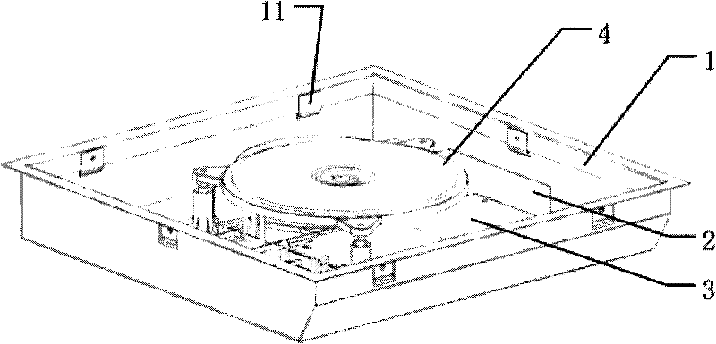
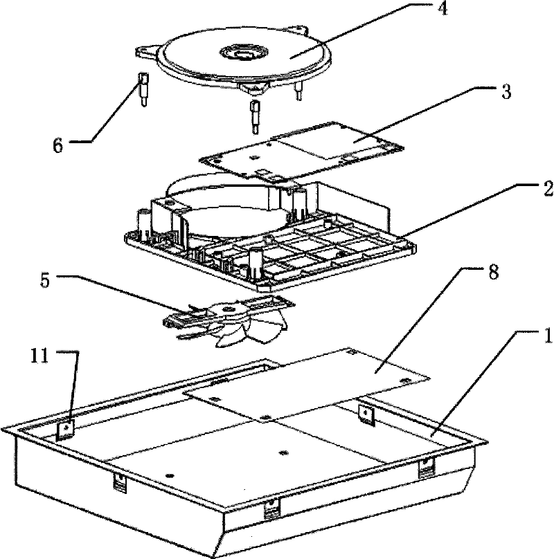
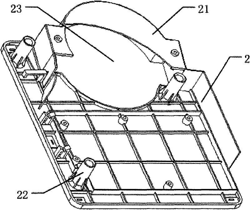
[0022] like Figure 1 to Figure 4 As shown, it is a schematic view of the internal structure of the electromagnetic oven of the present invention after removing the ceramic plate, a schematic view of the decomposition, a schematic view of the structural appearance of the plastic tray, and a schematic cross-sectional view of the assembly of the coil.

[0023] It can be seen from the figure that all functional components of the assembled induction cooker except the ceramic plate are installed in the base of the metal shell. The induction cooker structure includes: a base 1 of a metal shell, an upper cover assembly covering the base (respectively including a ceramic plate and an upper cover frame not shown), and a circuit board 3 and a wire reel 4 installed in the induction cooker body. ...


PUM


Abstract

The invention discloses an induction cooker structure. The induction cooker structure comprises a foundation of a metal shell, an upper cover assembly which is covered on the foundation, and a circuit board and a wire coil which are arranged in an induction cooker body; the upper cover assembly comprises a ceramic plate and an upper cover frame; the induction cooker structure is characterized in that: a plastic tray which is arranged in the foundation is arranged in the induction cooker; the circuit board and the wire coil are fixedly connected with the plastic tray respectively; a flow guide cover plate is integrally formed on the plastic tray through injection molding; and a fan is arranged at the bottom of the tray at one end of the flow guide cover plate and is connected with the circuit board and driven, and an air outlet at the other end of the flow guide cover plate is opposite to heating parts of the induction cooker respectively. In the induction cooker structure, the internal structure of a plastic induction cooker is stimulated in the metal shell by using the plastic tray, so that the heat radiation performance in the induction cooker is improved, the service life of components of a large-power induction cooker is effectively prolonged, and simultaneously, the assembly process during production is simplified.

Description

technical field [0001] The invention relates to an electric device, in particular to a shell assembly structure of a high-power electromagnetic cooker with a metal shell. Background technique [0002] As the pace of the kitchen revolution is accelerating day by day, in consideration of sanitation and energy saving, induction cookers are gradually replacing traditional gas stoves and becoming an indispensable food processing equipment in the kitchen. From the current point of view: a big problem closely related to the life of the induction cooker is the heat dissipation inside the machine. In a common plastic single furnace, a plastic structure can be used to make an air duct, so that the wind of the cooling fan can be guided to the heat sink of the insulated gate bipolar transistor (hereinafter referred to as IGBT) and the bridge, and on the coil. IGBT, bridge and reel are the three components with the highest temperature in the induction cooker, and they are also the three...

Claims


Application Information

Patent Timeline
IPC IPC(8): F24C7/00F24C15/00
Inventor 胡学青庞惠明邵军
Owner 苏州市春和电器有限公司
Learn More