Method of fabricating structures using composite modules and structures made thereby

A composite structure and composite mold technology, which is applied in the field of manufacturing composite structures, can solve problems such as large capital investment, and achieve the effects of high material laying speed, reduced production time, and high yield

Active Publication Date: 2011-09-21
THE BOEING CO
View PDF8 Cites 12 Cited by
  • Summary
  • Abstract
  • Description
  • Claims
  • Application Information

AI Technical Summary

Problems solved by technology

One way to obtain a higher unit yield can be done by providing a higher number of AFP machines, however, the use of additional

Method used


Image

  • Method of fabricating structures using composite modules and structures made thereby
  • Method of fabricating structures using composite modules and structures made thereby
  • Method of fabricating structures using composite modules and structures made thereby

Examples


Embodiment Construction

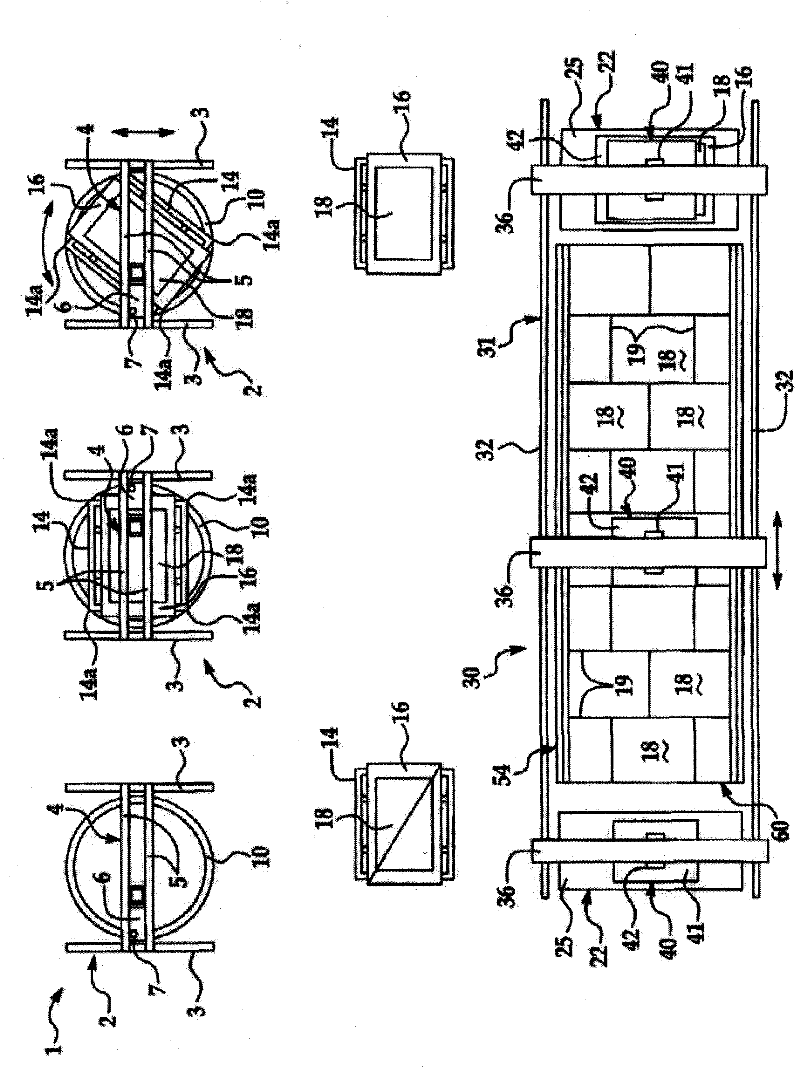
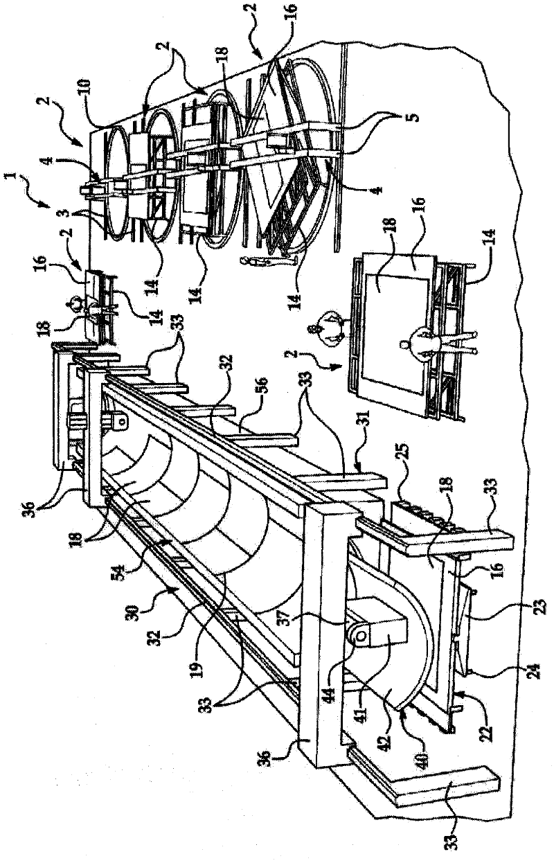
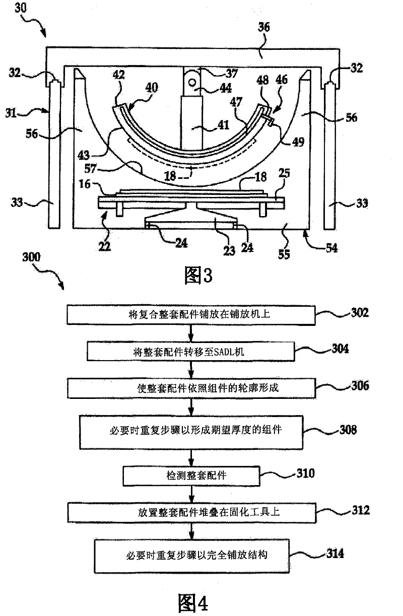
[0087] First refer to the attached Figure 1-3 , a manufacturing system suitable for the practice of the illustrative embodiment of the modular composite manufacturing method is indicated generally by reference numeral 1 . manufacturing system 1 with figure 1 top view in and figure 2 The perspective view in is shown. Modular composite manufacturing methods may use simple appropriately sized equipment to ensure that composite material is laid up in a parallel process rather than in series as fabricated components of a composite aircraft fuselage or other components. Using parallel process methods to automatically laminate aircraft fuselage skin modules or other components can greatly reduce the process time required to manufacture individual components. This could reduce the capital investment, factory floor space and logistical staff required to manufacture composite aircraft fuselage skins or other components. Furthermore, the method may be used to manufacture flat-lay-u...


PUM


Abstract

A large scale composite structure is fabricated by forming a plurality of composite laminate modules (208d, 208e) and joining the modules together along their edges (210) using scarf joints.

Description

technical field [0001] The present disclosure relates generally to techniques for fabricating composite structures, and more particularly to methods of fabricating large composite structures by joining composite modules together. Background technique [0002] Large composite structures such as aircraft fuselage skins can be manufactured using Advanced Fiber Placement (Advanced Fiber Placement, AFP) machines capable of laying down composite material at relatively high rates. One way to obtain a higher unit yield can be accomplished by providing a greater number of AFP machines, however, the use of additional AFP machines may result in the need for a substantial capital investment in terms of machine cost, process and factory floor space. [0003] Accordingly, there is a need for relatively high yield manufacturing methods with low capital investment and production costs. There is also a need for a manufacturing method that is relatively flexible and relies on simpler equipme...

Claims


Application Information

Patent Timeline
IPC IPC(8): B64C1/12B64F5/00
CPCB64C2001/0072Y02T50/43Y02T50/433B29C70/38B29L2031/3082B64F5/0009B29C70/30B29C70/545B64F5/10Y10T156/1002Y10T29/49622Y10T29/49861Y10T428/192Y10T156/1052B29C31/08Y02T50/40B29C70/304B29C70/50B32B3/02B64C1/12B64F5/00B29K2105/0872B29K2307/04
Inventor D·D·琼斯A·J·伯格J·D·布里南T·J·谢伍德
Owner THE BOEING CO
Why Eureka
Try Eureka