Take-up vacuum processing device

A vacuum processing device, winding technology, applied in the direction of gaseous chemical plating, coating, electrical components, etc., can solve problems such as damage and loss of the service life of the collector ring

Active Publication Date: 2011-09-21
ULVAC INC
View PDF5 Cites 13 Cited by
  • Summary
  • Abstract
  • Description
  • Claims
  • Application Information

AI Technical Summary

Problems solved by technology

[0008] When the slip ring is used as a connection part of a high-frequency power supply, it may be damaged by heat
In addition, since the electrodes of the collector ring are contact electrodes, the electrodes will be worn due to mutual contact, thus detrimental to the service life of the collector ring

Method used


Image

  • Take-up vacuum processing device
  • Take-up vacuum processing device
  • Take-up vacuum processing device

Examples


Embodiment Construction

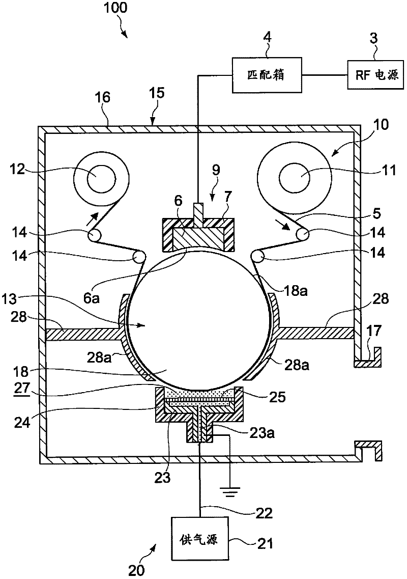
[0018] A wound vacuum processing apparatus according to an embodiment of the present invention includes a vacuum chamber, a first electrode, a gas supply unit, and a third electrode.

[0019] The internal state of the vacuum chamber may be maintained in a vacuum state.

[0020] The first electrode is a roller electrode that is rotatably installed in the vacuum chamber, and is rotated and held in contact with the soft object to be processed so that the object to be processed can be conveyed.

[0021] The gas supply unit has a second electrode disposed facing the first electrode in the vacuum chamber, and can supply processing gas between the object to be processed and the second electrode, and the object to be processed and the object to be processed are the first electrode contact.

[0022] The third electrode is disposed facing the first electrode in the vacuum chamber, and an AC voltage is applied between the third electrode and the first electrode by the AC power supply. ...


PUM


Abstract

Provided is a take-up vacuum processing device which prevents damage due to heat generation and occurrence of dielectric breakdown, thereby being suitable for life extension. An RF electrode (6) is disposed in a vacuum chamber (15). Accordingly, for example, compared to when a rotation introducing unit such as a capacitor coupling is disposed under atmospheric pressure, the occurrence of dielectric breakdown between a roller electrode (18) and the RF electrode (6) can be prevented if the interior of the vacuum chamber (15) is maintained at a predetermined degree of vacuum. Moreover, the problem of damage due to heat generation in conventional rotation introducing units such as a rotary connector is eliminated. Since the RF electrode (6) is disposed with a gap from the roller electrode (18), that is, since alternating-current voltage is applied to the roller electrode (18) without contact, wear due to contact does not occur, and thus the life extension of the electrodes can be achieved.

Description

technical field [0001] The invention relates to a winding-type vacuum processing device, which can continuously send out soft objects to be processed in a vacuum environment and make the processed objects sent out close to a cylindrical roller, and then treat the processed objects on the cylindrical roller The object is subjected to a predetermined treatment, and then the processed object is taken up. Background technique [0002] Conventionally, a thin film forming apparatus is known which forms a thin film on a substrate of the magnetic recording medium while continuously feeding and winding the magnetic recording medium by rollers. In the thin film forming apparatus described above, while the magnetic recording medium is conveyed in close contact with the rotating drum roll, plasma is generated by a reactive gas between the drum and the first anode provided facing the drum. Thereby, a protective film can be formed on a magnetic recording medium (for example, refer patent...

Claims


Application Information

Patent Timeline
Patent Type & Authority Applications(China)
IPC IPC(8): C23C16/509
CPCC23C16/545C23C16/505H01J37/3277C23C16/52
Inventor 广野贵启多田勋
Owner ULVAC INC
Why Eureka
Try Eureka