Temperature field testing system for exhaust plume of engine analogue combustion device and testing method thereof

A combustion device and testing system technology, which is applied in the testing of engines, testing of machinery/structural components, thermometers using electrical/magnetic components that are directly sensitive to heat, etc. Effect

Inactive Publication Date: 2013-01-23
PLA AIR FORCE OIL MATERIAL RES INST
View PDF0 Cites 0 Cited by
  • Summary
  • Abstract
  • Description
  • Claims
  • Application Information

AI Technical Summary

Problems solved by technology

However, most of these studies are based on combustion diagnosis and testing of boiler furnace flames.
There is no measurement of the temperature field of the exhaust plume when the aircraft engine is working

Method used


Image

  • Temperature field testing system for exhaust plume of engine analogue combustion device and testing method thereof
  • Temperature field testing system for exhaust plume of engine analogue combustion device and testing method thereof
  • Temperature field testing system for exhaust plume of engine analogue combustion device and testing method thereof

Examples


Embodiment 1

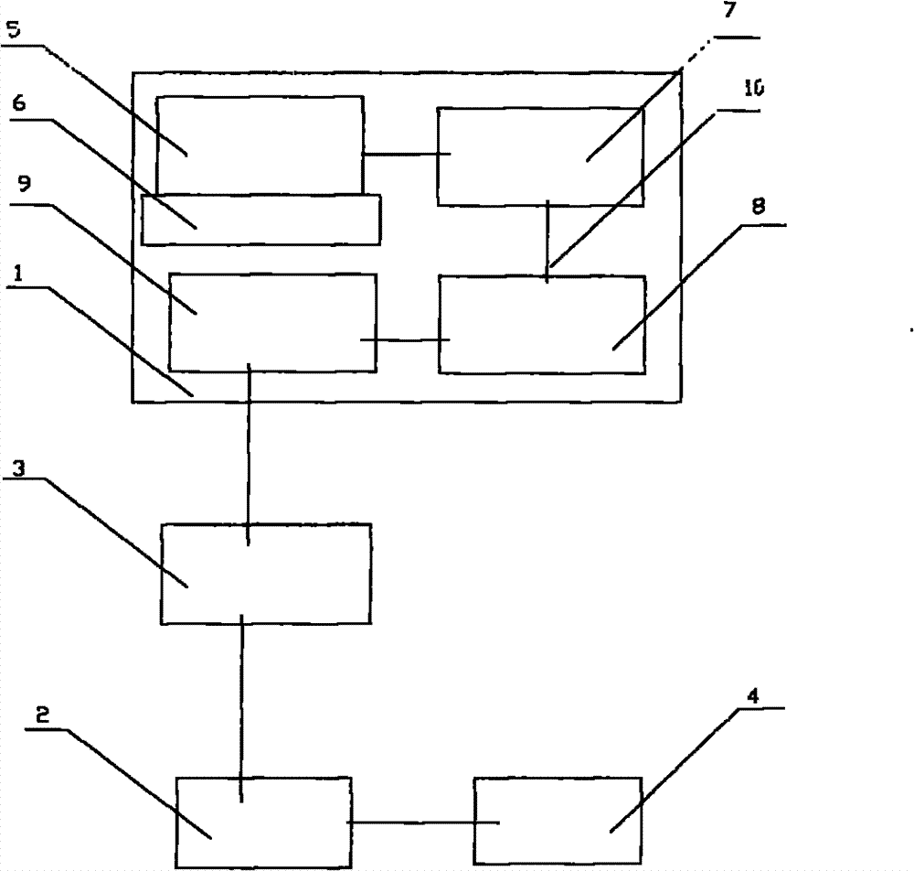
[0035] A temperature field test system for an engine simulating combustion device jet tail flame, which includes: a combustion device data acquisition system 1, a fuel consumption device control system 2, and a data processing system 3, and the combustion device data acquisition system 1 passes electrical signals or data The signal is connected to the data processing system 3, the fuel consumption device control system 2 is connected to the data processing system 3 through electrical signals or data signals, and the fuel consumption device control system 2 is connected to the engine simulation combustion device 4 through electrical signals or data signals.

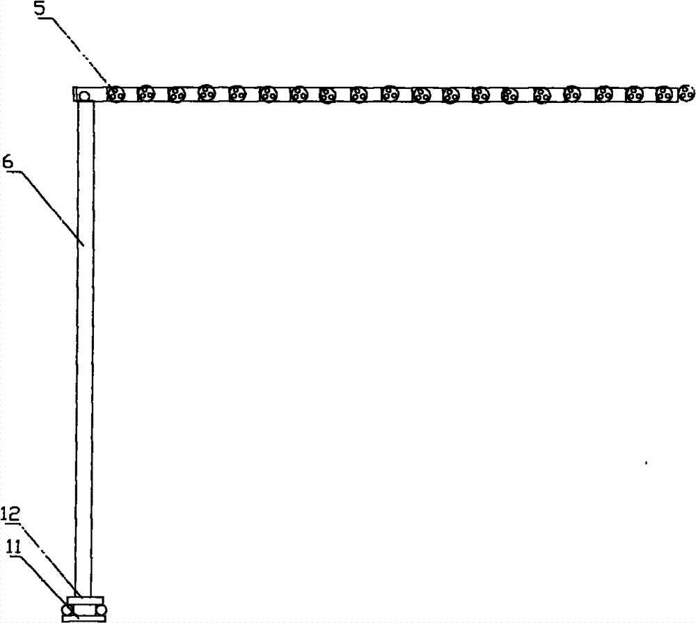
[0036] The combustion device data acquisition system 1 includes: a thermocouple group 5, a thermocouple fixed support 6, a temperature transmitter 7, a signal conversion module 8, and a combustion device data acquisition card 9; the thermocouple group 5 is erected on the thermocouple fixed support 6 and connected to the tem...

Embodiment 2

[0043]Comprising a track 11 and a mobile control system, the mobile control system includes a mobile control module and a mobile controller 12, the mobile controller 12 is arranged on the track 11, is connected with the mobile control module by electrical signals, and the thermocouple fixing bracket is fixed on On the mobile controller, during the measurement process, the mobile control module can send electrical signals to control the movement of the mobile controller, and the mobile controller drives the thermocouple fixed bracket to move, so that the thermocouple probe can be moved flexibly and accurately to obtain different positions in different areas The data. The thermocouple set includes 3 thermocouple probes. All the other are with embodiment 1.

Embodiment 3

[0045] Select the test state and test range; for a simulated flame-throwing device, select a working state as a stable working state, such as the selected fuel type is RP-3 jet fuel, and the fuel flow rate for combustion and fuel supply is 6.0g / s, the air supply flow rate is 0.60kg / s, and the average temperature of the nozzle is 780K. In this working state, use a method to measure and describe the temperature distribution in the three-dimensional space formed by the rotation of the center line of the nozzle in the direction of the flamethrower, with the center line of the nozzle as the axis of symmetry and the radius of 30cm. . In the tests, the length of this axis was 180 cm. During the test, the length of this axis is taken as 180cm, and the temperature in the space of a cylinder formed by rotating around this axis with a radius of 30cm is taken as the research object. As the common sense of scientific and technical personnel can know, the temperature field change of the ...


PUM

PropertyMeasurementUnit
lengthaaaaaaaaaa

Abstract

The invention relates to a temperature field testing system for exhaust plume of an engine analogue combustion device and a testing method thereof, belonging to the technical field of testing equipment and methods. The temperature field testing system disclosed by the invention consists of a combustion device data collecting system, a fuel combustion device control system and a data processing system. The testing method comprises the following steps: dividing planar grids and installing the testing system after choosing the testing status and testing scope; controlling the combustion device control system by means of a computer to start the exhaust plume of the analogue combustion device so as to obtain the relevant data; and sorting out and calculating the data by computer. The method inthe invention is easy, structure is simple and the design is scientific and reasonable. Besides, in the invention, the problem that the no apparatus can be used for testing the airplane engine analogue combustion device in the prior art can be solved. The status and various data of the airplane in working conditions can be known via temperature field testing for exhaust plume of the engine analogue combustion device.

Description

technical field [0001] The invention relates to a testing method and equipment, in particular to a temperature field testing system for an engine simulating combustion device jet tail flame and a testing method using the system. Background technique [0002] The tail flame is the high-temperature, high-speed airflow ejected by the aircraft engine. It is of great significance to study the infrared radiation characteristics of the aircraft tail flame, which can provide reliable data for infrared homing and infrared protection. To study the infrared radiation intensity of the plume, it is necessary to know the temperature field, pressure field and composition of the plume. It is of great significance to study the temperature, pressure and composition of the plume for better infrared stealth technology of the plume. In order to quickly and simply measure the temperature distribution field of the tail flame ejected from the simulated combustion device of the turbojet engine in t...

Claims


Application Information

Patent Timeline
Patent Type & Authority Patents(China)
IPC IPC(8): G01K7/02G01M15/00
Inventor 赵升红朱春婷张冬梅黄毅安军伟刘鹏瑞刘建华
Owner PLA AIR FORCE OIL MATERIAL RES INST
Why Eureka
Try Eureka