
Symmetrical half-bridge LLC resonant bidirectional DC-DC converter

A DC converter, bidirectional DC technology, applied in the direction of converting DC power input to DC power output, instruments, regulating electrical variables, etc., can solve the difficulty of optimal design of filters and closed-loop controllers, and the difficulty of converters to achieve soft switching. Affect the energy conversion efficiency of the converter and other issues, and achieve the effects of improving electromagnetic compatibility, alleviating transient overvoltage and transient overcurrent, and reducing volume and weight.

Active Publication Date: 2011-09-28
NORTH CHINA ELECTRIC POWER UNIV (BAODING)
View PDF3 Cites 51 Cited by
  • Summary
  • Abstract
  • Description
  • Claims
  • Application Information

AI Technical Summary

Problems solved by technology

Similar to the unidirectional zero-voltage switching PWM bridge DC-DC converter, the energy stored in the energy storage inductor or the leakage inductance of the isolated high-frequency transformer is used to realize the zero-voltage switching of the bridge arm. The disadvantage is that the converter has a large internal Circulating energy affects the improvement of the energy conversion efficiency of the converter, especially when the converter is light-loaded, it is difficult to achieve soft switching
The application of resonance eliminates the overlapping phenomenon of voltage and current during the switching process of the switching device in the converter, and reduces the switching loss of the switching device. However, the converter needs to work with frequency conversion, so that the filter of the converter and the closed-loop controller It is difficult to optimize the design. In addition, there are defects such as large voltage and current stress in the converter.

Method used


Image

  • Symmetrical half-bridge LLC resonant bidirectional DC-DC converter
  • Symmetrical half-bridge LLC resonant bidirectional DC-DC converter
  • Symmetrical half-bridge LLC resonant bidirectional DC-DC converter

Examples


Embodiment Construction

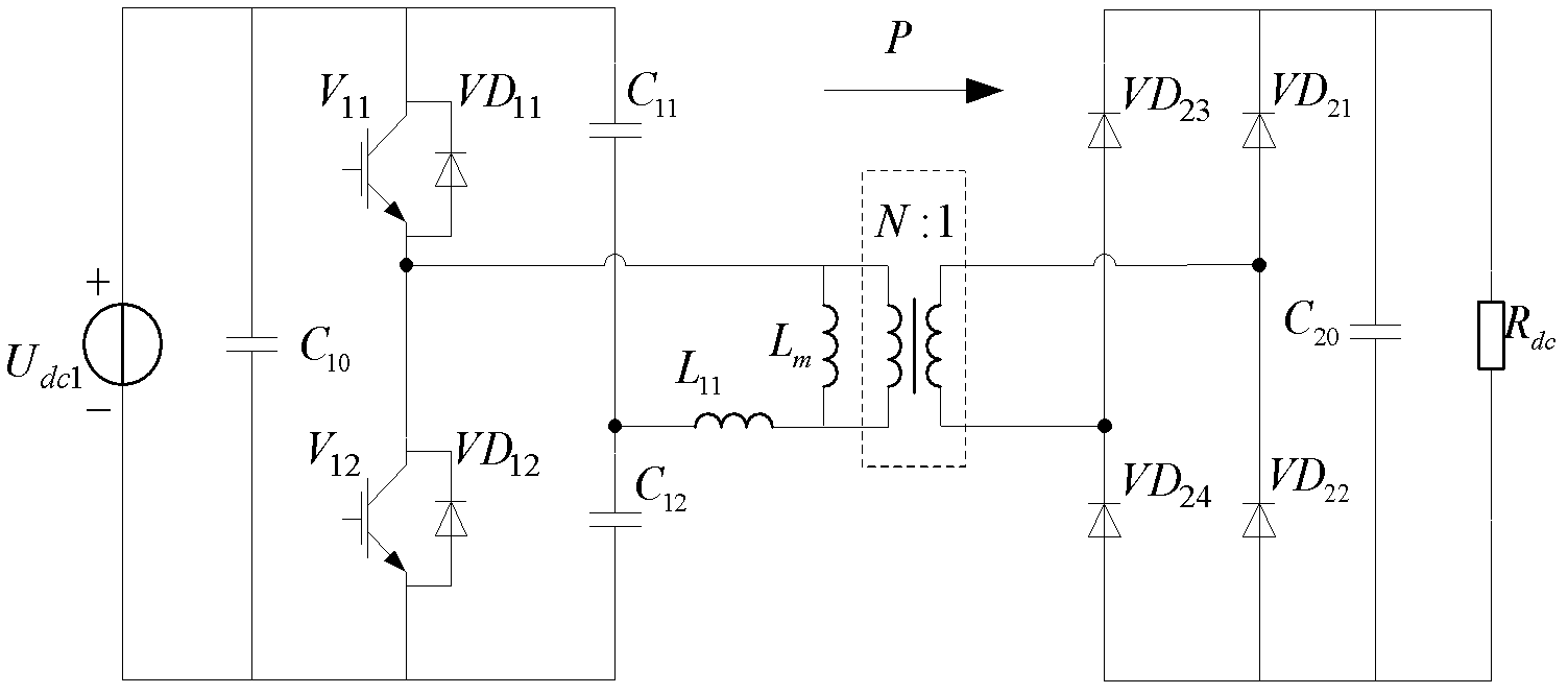
[0033] The invention proposes a symmetrical topological structure of an LLC resonant bidirectional DC-DC converter and a control method thereof. The present invention will be described below in conjunction with the accompanying drawings.

[0034] Such as figure 1 As shown, the power transmission of the converter is divided into forward power transmission and reverse power transmission, and the forward power transmission of the converter is the transmission of power from port 1-1' to port 2-2' , the reverse power transmission of the converter is the transmission of power from port 2-2' to port 1-1'. The converter is composed of a switch network, a resonant network and a rectifier-load network in series, centered on a T high-frequency transformer , the circuit on the left side is symmetrical to the circuit on the right side.

[0035] When the converter performs forward power transmission, the connection relationship of the switch network is as follows: anti-parallel VD 11 The...


PUM


Abstract

The invention discloses a symmetrical half-bridge LLC resonant bidirectional DC-DC converter, which belongs to the technical field of power electronic application. Topological structures on the two sides of the converter are symmetrical, and adopted components adopt a complex function design. When a switching network and a resonant network on one side of a high frequency transformer function, the switching network and the resonant network on the other side are automatically evolved into a rectifier-load network, and the networks on the two sides commonly form the whole LLC resonant converter to realize power conversion in a corresponding direction. Because the structures are completely symmetrical, reverse conversion can be possible; and in the reverse conversion, the topological structures can be automatically reconstructed to form a reverse LLC resonant converter to realize reverse power conversion. The symmetrical half-bridge LLC resonant bidirectional DC-DC converter achieves effective improvements in conversion efficiency, power density, dynamic performance and electromagnetic compatibility, reduces the electrical stress of components at work, has a reduced volume and a reduced weight, and realizes highly-efficient, isolated and bidirectional DC / DC power conversion.

Description

technical field [0001] The invention belongs to the technical field of power electronics applications, and in particular relates to a symmetrical half-bridge LLC resonant bidirectional DC-DC converter. Background technique [0002] A bidirectional DC-DC converter refers to a DC-DC converter that can change the direction of energy transmission as needed while maintaining the polarity of the DC voltage on both sides of the converter. Compared with the scheme of using two sets of unidirectional DC-DC converters to achieve bidirectional energy transmission, the bidirectional DC-DC converter uses the same converter to achieve bidirectional energy transmission, and the overall number of devices used is less, which can be more quickly The switching of power conversion in two directions has the advantages of high efficiency, small size, good dynamic performance, and low cost. In the face of rapid changes in the global environment, energy shortages, and rising pressure on energy con...

Claims


Application Information

Patent Timeline
Patent Type & Authority Applications(China)
IPC IPC(8): H02M3/338
CPCY02B70/1433Y02B70/10
Inventor 颜湘武张波董清
Owner NORTH CHINA ELECTRIC POWER UNIV (BAODING)
Learn More