System and method of dynamically building a behavior model on a hardware system

A hardware system and dynamic technology, applied in computer-aided design, special data processing applications, program control devices, etc., can solve the problems of extended development cycle and achieve the effect of cost-effective, effective development cycle, and fast time to enter the market

Inactive Publication Date: 2011-09-28
ENGINELAB
View PDF2 Cites 6 Cited by
  • Summary
  • Abstract
  • Description
  • Claims
  • Application Information

AI Technical Summary

Problems solved by technology

In case of behavioral model design changes, the entire sequence of 2-9 must be repeated, which in turn leads to an extended development cycle

Method used


Image

  • System and method of dynamically building a behavior model on a hardware system
  • System and method of dynamically building a behavior model on a hardware system
  • System and method of dynamically building a behavior model on a hardware system

Examples


Embodiment Construction

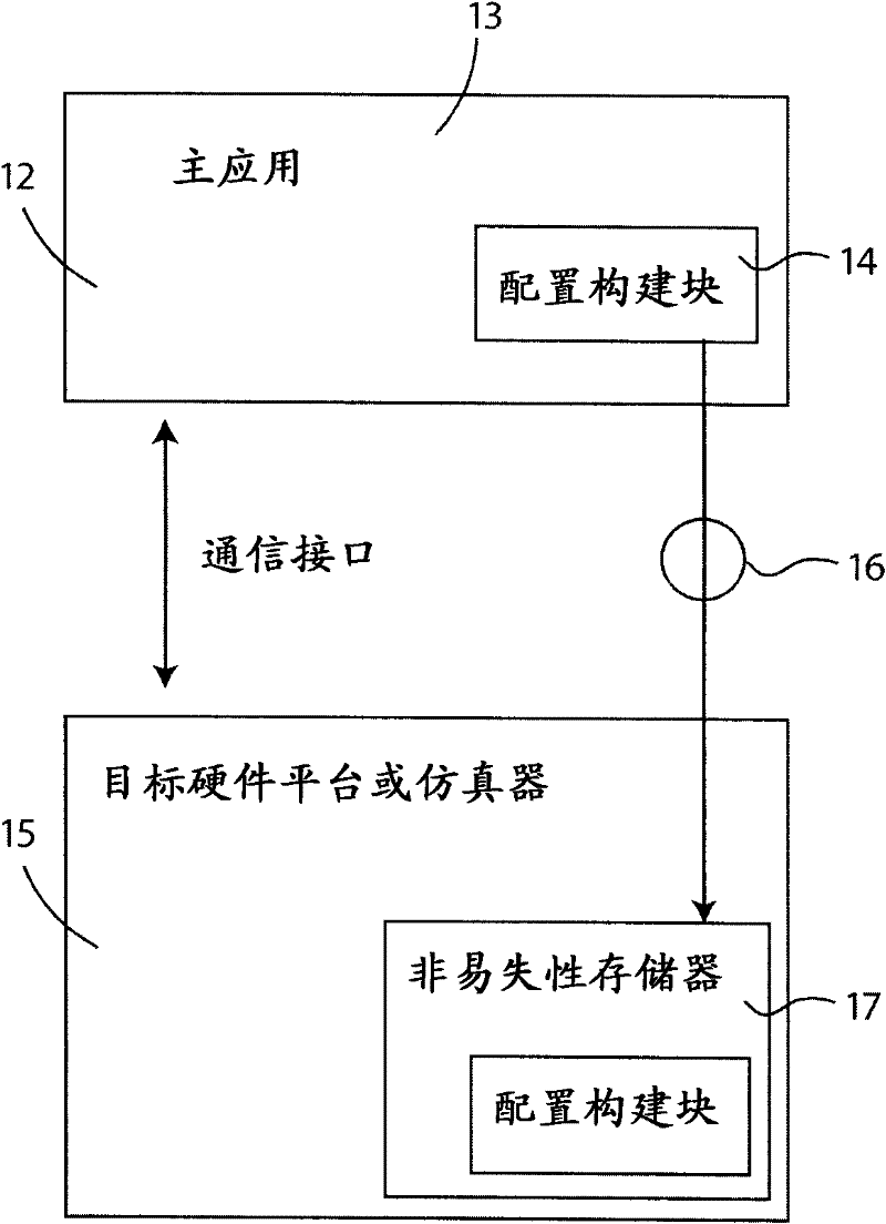
[0020] Embodiments of the present invention relate to the dynamic construction of behavioral models directly on the hardware platform. The electronic control system is referred to as an object in this invention. The electronic control system is the hardware platform that is the design target of the behavioral model. A behavioral model will be built dynamically on the target hardware system, enabling the hardware platform to read inputs and control outputs to produce the desired control system behavior. The host system is the development platform that developers can connect to the target hardware platform. The host system is usually a personal computer, but can be any system capable of communicating with the target using the correct communication protocol.

[0021] image 3 Describes the connection of the host system to the target system. 12 depicts the host system and 13 represents an application program running on the host computer capable of communicating with the target...


PUM


Abstract

A control system is dynamically built directly on a target hardware system. A host application on a host computer provides an interface to download configuration building blocks for the control system directly onto the target hardware. The host application is used to define building block type and connectivity. Microprocessor execution control of the system as well as block priority can likewise by defined by the host application.

Description

[0001] Cross References to Related Applications [0002] This application claims the benefit of US Provisional Application No. 61 / 110,840, filed November 3, 2008, which is hereby incorporated by reference in its entirety, including all drawings, tables and drawings. [0003] Statement Involving Federally Sponsored Research or Development [0004] Not applicable [0005] CD-ROM attachments referring to sequence listings, tables, or computer program listings [0006] Not applicable technical field [0007] The present invention relates to building behavioral models for electronic hardware control systems - in particular to dynamically building behavioral models directly on production hardware platforms. Background technique [0008] This application concerns the design of electronic control systems. Various types of systems utilize processors to control the system. An example of a system is an automatic controller that manages the operation of a car. Another example syst...

Claims


Application Information

Patent Timeline
Patent Type & Authority Applications(China)
IPC IPC(8): G06F9/44
CPCG06F17/505G06F30/327
Inventor J·维托P·布朗
Owner ENGINELAB
Why Eureka
Try Eureka