

Method for welding zirconium alloy tube connector for explosion bulge test
A welding method and blasting test technology, which is applied to welding equipment, applications, household appliances, etc., can solve the problems of low test success rate and waste of manpower and material resources, and achieve the effect of improving the success rate and saving raw materials
- Summary
- Abstract
- Description
- Claims
- Application Information
AI Technical Summary
Problems solved by technology
Method used
Image

Examples
Embodiment 1
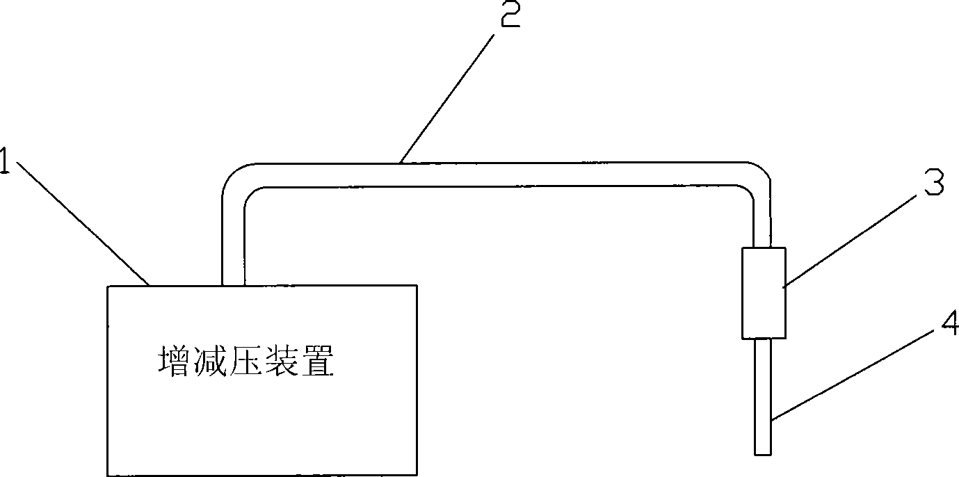
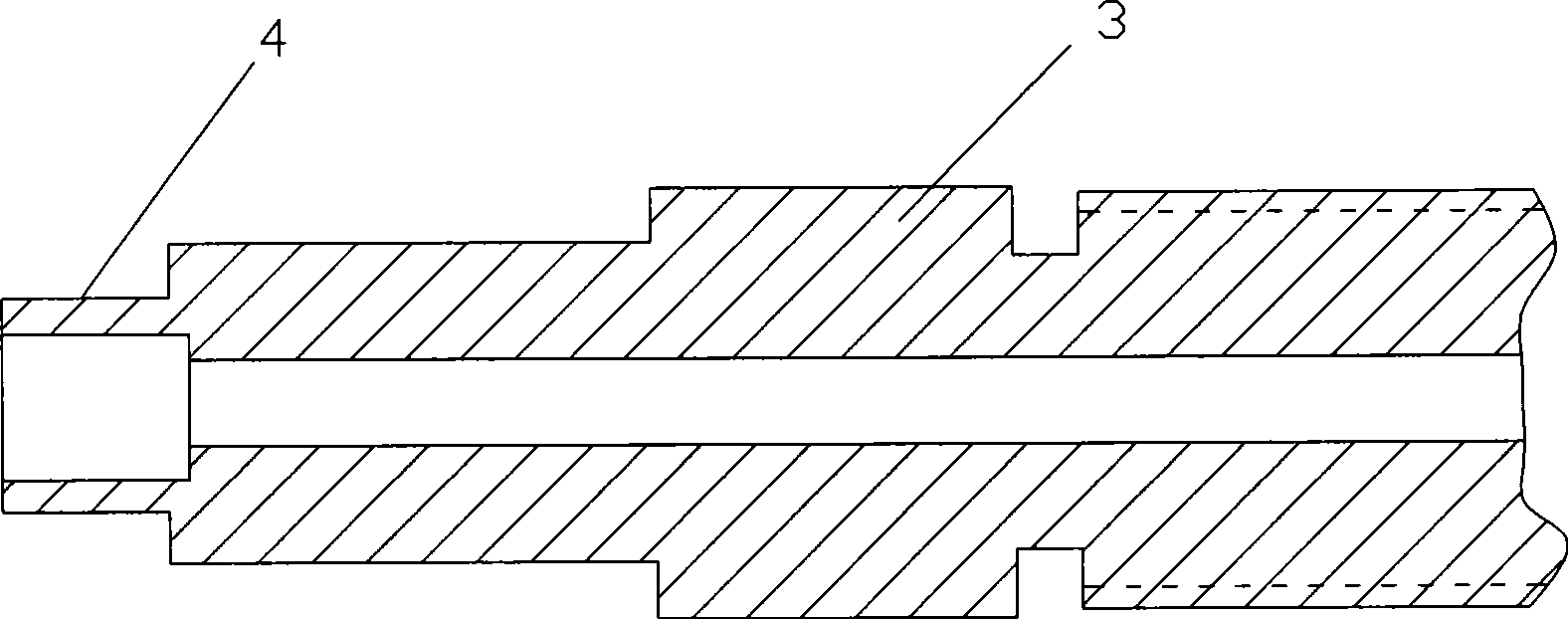
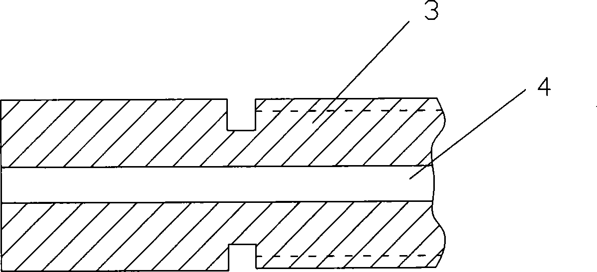
[0012] For 6 Zr-4 pipes with an outer diameter of 6mm and a length of 150mm, one end is welded with an end plug, the inner diameter of the coupling joint 3 is processed to 6.5~6.8mm, and the open end of the pipe 4 is shown image 3 The inner hole of end A is inserted to end B and protrudes about 1mm, and argon arc welding is performed around end B to the coupling joint 3 and the sleeve pipe 4. After the welding is completed, the flat head is machined to facilitate the sealing connection. All the 6 sleeved pipes were tested successfully, and none of them broke at the weld.
Embodiment 2
[0014] The test was performed on 6 Zr-4 pipes with an outer diameter of 8 mm and a length of 150 mm. The method was the same as in Example 1, except that the inner diameter of the coupling joint was changed. The test success rate was 100%.
PUM
| Property | Measurement | Unit |
|---|---|---|
| length | aaaaa | aaaaa |
Abstract
Description
Claims
Application Information