Force-controlled electromagnetic permanent magnetic composite excitation vibration platform

A composite excitation and shaking table technology, applied in vibration testing, fluids utilizing vibration, measuring devices, etc., can solve the problems of inability to realize low frequency drive, many components and links, and inability to realize efficient direct drive and high reliability drive, etc. Achieve the effects of good rigidity, precise and controllable vibration displacement, and simple mechanism

Active Publication Date: 2013-01-09
SHANGHAI JIAOTONG UNIV
View PDF1 Cites 0 Cited by
  • Summary
  • Abstract
  • Description
  • Claims
  • Application Information

AI Technical Summary

Problems solved by technology

[0004] However, this prior art is realized through the driving form of voice coil motor "equipped with a moving coil", and requires drive transmission links such as the drive motor and the screw rod connected to it.
In this way, the vibration equipment based on the dynamic coil drive is difficult or impossible to achieve low-frequency drive within 5 Hz, and its drive involves many components and links. The drive also requires the motor and the screw and screw mechanism to follow the movement by controlling the traction carriage. The synchronous movement of the platform, as well as the side effects such as the involvement of the intake pipe and the lead wire and additional force, make the entire platform unable to achieve efficient direct drive and high reliability drive

Method used


Image

  • Force-controlled electromagnetic permanent magnetic composite excitation vibration platform
  • Force-controlled electromagnetic permanent magnetic composite excitation vibration platform
  • Force-controlled electromagnetic permanent magnetic composite excitation vibration platform

Examples


Embodiment 1

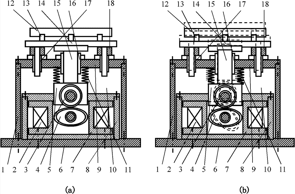
[0029] Such as figure 1 As shown, this embodiment includes: a housing 1, an electromagnetic coil 2, a magnetic energy body 3, 4 and an object-carrying mechanism 5, wherein: two magnetic energy bodies 3, 4 are arranged up and down inside the housing 1 in a horizontal rotating shaft manner and mutually In contact, the electromagnetic coil 2 is located inside the housing and facing the second magnetic energy body 4, and the object-carrying mechanism 5 is movably arranged on the top of the housing 1 and is in contact with a magnetic energy body.

[0030] The housing 1 includes: a base 6, a rotating shaft support frame 7, a magnetic circuit inner frame 8 and a fuselage outer frame 9, wherein: the fuselage outer frame 9 is fixedly connected to the base 6, the rotating shaft support frame 7 and the magnetic circuit The inner frame body 8 is respectively fixed in the outer frame body 9 of the fuselage and located inside and outside the electromagnetic coil 2 .

[0031] The inside of ...

Embodiment 2

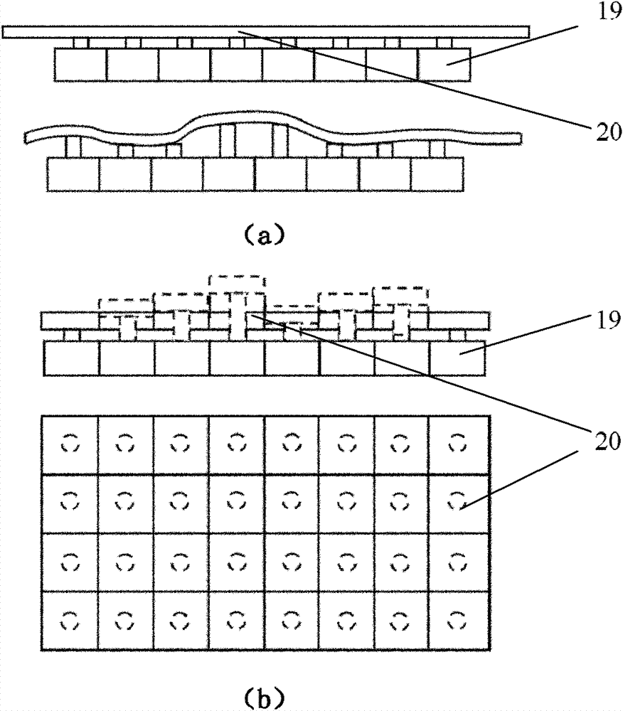
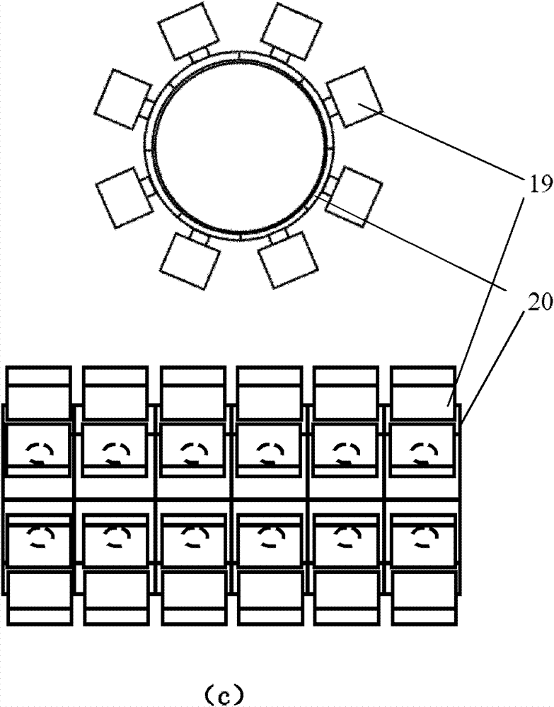
[0045] Such as figure 2 As shown, in this embodiment, by arranging the above-mentioned several force-controlled electromagnetic permanent magnet compound excitation vibration tables 19 in a linear array, a planar array or a three-dimensional array, the corresponding driven body or driven body array 20 is excited, And independently control or parallel or connect its electromagnetic coils to form a corresponding force-controlled electromagnetic permanent magnet composite excitation vibration system, which can be used to simulate and realize anti-vibration and anti-external load experiments on large facilities with long "length" such as bridges Test work, used to simulate the anti-vibration and anti-external load experimental test research on the impact of vehicles and large buildings such as road surfaces, waves, earthquakes, etc. or used to simulate the realization of three-dimensional external loads on vehicles and large buildings Experimental research on resistance to extern...


PUM


Abstract

The invention discloses a force-controlled electromagnetic permanent magnetic composite excitation vibration platform in the technical field of electromagnetic drivers. The force-controlled electromagnetic permanent magnetic composite excitation vibration platform comprises a shell, electromagnetic coils, magnetic energy bodies and a carrying mechanism, wherein the two magnetic energy bodies are respectively arranged inside the shell in a manner of a horizontal rotating shaft and are in mutual contact, the two electromagnetic coils are respectively arranged inside the shell and positioned at two sides of the magnetic energy bodies, and the carrying mechanism is movably arranged on the top of the shell and is in contact with one magnetic energy body. The force-controlled electromagnetic permanent magnetic composite excitation vibration platform is a wide-band large-load and large-displacement vibration device or equipment which has the advantages of simple structure, high reliability and drive efficiency, no moving coil and lead following dragging hidden dangers, accuracy and controllability of amplitude and capability of realizing frequency of below 5Hz, i.e. from quasi-static to high frequency, and is driven by direct displacement generated by the electrically-excited rigid magnetic energy bodies.

Description

technical field [0001] The invention relates to a device in the technical field of electromagnetic drives, in particular to a force-controlled electromagnetic permanent magnet composite excitation vibration table. Background technique [0002] In recent years, due to the need for vibration testing of aircraft or precision equipment in the fields of aerospace, aviation, and navigation, the demand for high-performance vibration testing equipment has become more and more urgent. At present, vibration equipment mainly includes hydraulic, pneumatic, electromagnetic and mechanical vibration equipment. Among them, hydraulic, pneumatic and mechanical vibration equipment can no longer meet the requirements of vibration test performance in aerospace and other fields due to the low drive frequency and many drive control links. Because the electromagnetic drive is controlled by electromagnetic signals, the realization of the drive is realized by the action of electromagnetic energy. Th...

Claims


Application Information

Patent Timeline
Patent Type & Authority Patents(China)
IPC IPC(8): G01M7/02B06B1/04
Inventor 杨斌堂孟光
Owner SHANGHAI JIAOTONG UNIV
Why Eureka
Try Eureka