
Noise shaping time to digital converter

A technology of digital converter and time, applied in the direction of time-to-digital converter, analog/digital conversion, code conversion, etc., can solve the problem of reducing the performance of TDC noise shaping

Active Publication Date: 2013-03-06
TELEFON AB LM ERICSSON (PUBL)
View PDF4 Cites 0 Cited by
  • Summary
  • Abstract
  • Description
  • Claims
  • Application Information

AI Technical Summary

Problems solved by technology

Conventional ring oscillator based TDCs are highly voltage dependent during stop and start periods, degrading the TDC's noise-shaping performance

Method used


Image

  • Noise shaping time to digital converter
  • Noise shaping time to digital converter
  • Noise shaping time to digital converter

Examples


Embodiment Construction

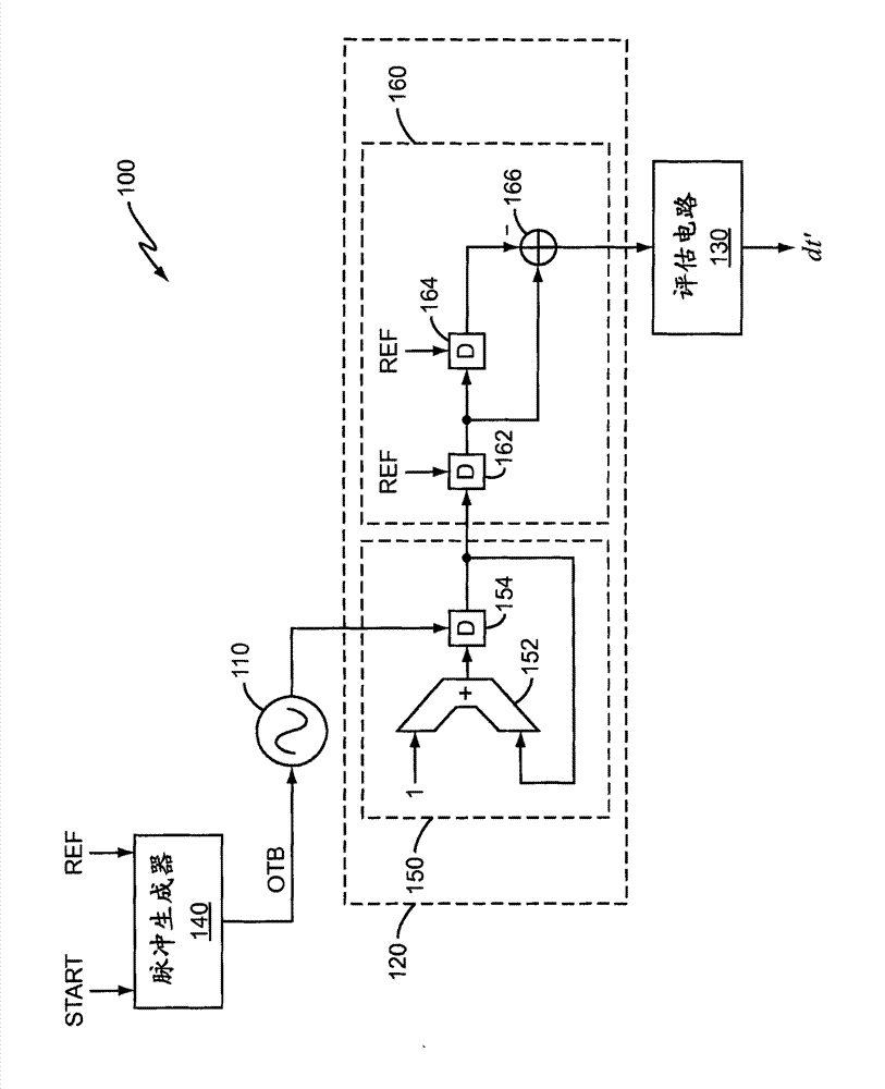
[0015] figure 1 An embodiment of a time-to-digital converter (TDC) 100 is illustrated. TDC 100 includes digitally controlled oscillator (DCO) 110 , counter circuit 120 , evaluation circuit 130 and pulse generator 140 . The TDC 100 utilizes noise shaping to provide very high resolution time measurements. When TDC 100 operates at a frequency (REF) that is multiple times higher than the bandwidth of the signal of interest (START), TDC 100 has a relatively high signal-to-noise ratio (SNR) compared to conventional non-noise-shaping TDCs. In addition, the TDC 100 performs quantization noise shaping by shifting the quantization noise towards higher frequencies. Optionally high frequency noise can be filtered, which results in a significant increase in SNR depending on the oversampling ratio employed by the TDC 100 .

[0016] The shaped quantization noise can be modeled as white noise filtered by a difference filter. In a sampled system, the transfer function of the differential f...


PUM


Abstract

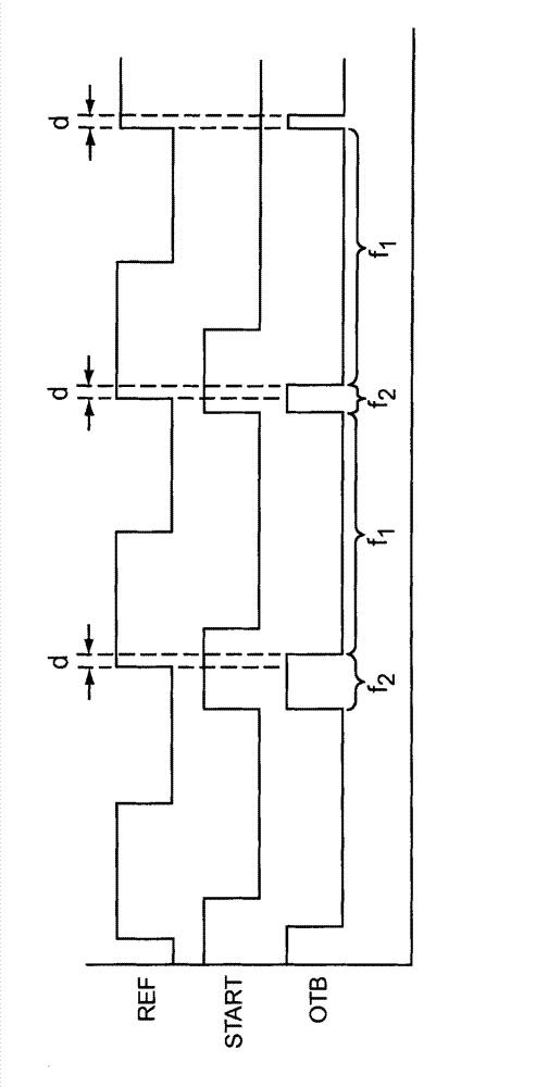
The time-to-digital converter operates as follows: by operating the numerically controlled oscillator (110) at a first frequency (f1) during the first part of the reference signal period and as a signal of interest (START) with the reference signal (REF) during the reference signal period The function of the time difference between changes the operating frequency from the first frequency to the second frequency (f2) to measure the time difference between the signal of interest and the reference signal. The time-to-digital converter continuously counts (150) how many signal transitions occur at the output of the digitally controlled oscillator during a period of the reference signal. A time difference between the signal of interest and the reference signal is estimated (130) based on the number of signal transitions counted during the reference signal period.

Description

technical field [0001] The present invention relates generally to time-to-digital converters, and more particularly to noise-shaping time-to-digital converters. Background technique [0002] A digital representation of the arrival time of each input pulse for a time-to-digital converter (TDC) output signal. A TDC can be formed by chaining together a string of inverters. A start pulse is propagated through the inverter chain and sampled with a stop pulse. The number of inverters the start pulse passes through provides a digital measure of the time from start to stop. The resolution associated with this type of TDC is usually limited by the inverter gate delay which is highly dependent on current, voltage and temperature. Also, the linearity of TDCs is limited by device mismatches and is usually traded off against speed and resolution. A smaller inverter stage is required to improve the resolution of the TDC because the smaller inverter reduces the parasitic capacitance. ...

Claims


Application Information

Patent Timeline
Patent Type & Authority Patents(China)
IPC IPC(8): H03M1/50G04F10/04H03L7/081
CPCG04F10/005H03L7/08H03L2207/50
Inventor S·埃克
Owner TELEFON AB LM ERICSSON (PUBL)
Learn More