Continuous countercurrent catalytic oxidation device of ventilation air gas of coal mine

A catalytic oxidation and wind gas technology, applied in gas emission, safety devices, mining equipment and other directions, can solve the problems of increasing system complexity, affecting the stable operation of the device, difficult maintenance, etc. Reduces the effect of airflow reversing systems

Inactive Publication Date: 2011-10-12
HUNAN UNIV OF SCI & TECH
View PDF7 Cites 3 Cited by
  • Summary
  • Abstract
  • Description
  • Claims
  • Application Information

AI Technical Summary

Problems solved by technology

The existing technology has the following disadvantages: (1) The exhaust air needs to be periodically reversed in the device to maintain the self-operation of the system
Piping, valves and control systems required to complete the reversing function add to the complexity of the system and are difficult to maintain
(2) At the moment of reversing, the pressure inside the device changes strongly, and it takes a while for the device to restore stability, which affects the stable operation of the device
(3) The reversing will also cause the exhaust air remaining in the pipeline and reactor to be discharged directly without being oxidized during the reversing

Method used


Image

  • Continuous countercurrent catalytic oxidation device of ventilation air gas of coal mine
  • Continuous countercurrent catalytic oxidation device of ventilation air gas of coal mine
  • Continuous countercurrent catalytic oxidation device of ventilation air gas of coal mine

Examples


Embodiment Construction

[0015] Below in conjunction with accompanying drawing and specific embodiment the present invention will be described in further detail:

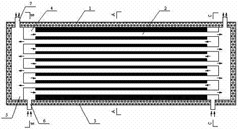
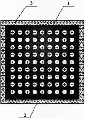
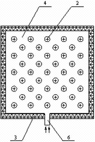
[0016] like figure 1 , figure 2 , image 3 and Figure 4 As shown, a continuous countercurrent catalytic oxidation device for exhaust gas in coal mines is composed of a ceramic regenerator 1, a circular channel 2, an insulating material 3, an air intake chamber 4, an exhaust chamber 5, an air intake pipe 6 and an exhaust pipe 7 Composition, the ceramic regenerator 1 is located in the center of the whole device, the two ends of the ceramic regenerator 1 are provided with an air intake chamber 4 and an exhaust chamber 5, and the circular channel 2 is along the length direction of the ceramic regenerator 1 Evenly arranged in it, the air intake chamber 4 is located at both ends of the circular passage 2 communicating with it, the air intake pipe 6 at both ends of the bottom communicates with the air intake chamber 4, and the exhaust chamber...


PUM


Abstract

The invention discloses a continuous countercurrent catalytic oxidation device of the ventilation air gas of a coal mine. The device consists of a ceramic heat storage body, a circular channel, a heat insulation material, air inlet chambers, air exhaust chambers, air inlet pipes and air exhaust pipes, wherein the ceramic heat storage body is positioned in the center of the whole device; the air inlet chambers and the air exhaust chambers are respectively arranged at two ends of the ceramic heat storage body; the circular channel is uniformly arranged in the ceramic heat storage body along the length direction of the ceramic heat storage body; the air inlet chambers are positioned at two ends of the circular channel which is communicated with the air inlet chambers; the air inlet pipes which are arranged at two ends of the bottom of the circular channel are communicated with the air inlet chambers; the air exhaust chambers are positioned at two ends of the circular channel which is communicated with the air exhaust chambers; the air exhaust pipes which are arranged at two ends of the top of the circular channel are communicated with the air exhaust chambers; and the heat insulation material is coated on the outermost layer of the device. In the device, ventilation air enters from two ends alternately, the direction of an air flow is not required to be changed, pipelines, valves and control elements for controlling the reverse direction of the air flow are eliminated, and the whole device is simple in structure and stable in operation.

Description

technical field [0001] The invention relates to a coal mine exhaust gas catalytic oxidation device, more specifically a coal mine exhaust gas continuous countercurrent catalytic oxidation device. Background technique [0002] Gas is the main greenhouse gas second only to carbon dioxide, and the greenhouse effect produced by a unit mass of gas is equivalent to 21 times that of the same mass of carbon dioxide. Coal mine exhaust gas is one of the main sources of methane emissions from the industry. Reducing the emission of coal mine exhaust gas can reduce greenhouse gas emissions. At the same time, the main component of coal mine gas is methane, which is a high-quality and clean gas energy source. The methane concentration in coal mine exhaust air is very low (generally less than 1%), and the concentration fluctuation range is large. These characteristics determine that it is difficult to use traditional burners to burn directly without auxiliary fuel. At present, almost all ...

Claims


Application Information

Patent Timeline
Patent Type & Authority Applications(China)
IPC IPC(8): E21F7/00
Inventor 冯涛王鹏飞陈丽娟郝小礼李石林贾真真姚琦
Owner HUNAN UNIV OF SCI & TECH
Why Eureka
Try Eureka