
Compression type exhaust gas self cooling system

A cooling system and compression technology, applied in the field of thermal energy and power, can solve the problems of exhaust energy loss, dissipation, bulky volume, etc., and achieve the effect of eliminating emissions and high-efficiency gas-phase closed cycle

Active Publication Date: 2015-06-03
张家港市乐余科创园投资发展有限公司
View PDF4 Cites 0 Cited by
  • Summary
  • Abstract
  • Description
  • Claims
  • Application Information

AI Technical Summary

Problems solved by technology

The temperature of the exhaust gas generally has a high temperature of seven to eight hundred degrees. The traditional method is to install a heat exchanger, but this method requires a large heat exchange area, and not only wastes the energy of the exhaust gas, but also needs to dissipate a large amount of energy. The power of the fan, so it has the disadvantages of bulky size and high power consumption

Method used


Image

  • Compression type exhaust gas self cooling system
  • Compression type exhaust gas self cooling system
  • Compression type exhaust gas self cooling system

Examples


Embodiment 1

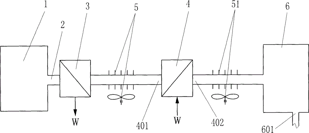
[0036] Such as figure 1 The compressed exhaust self-cooling system shown includes a thermodynamic system 1, a thermodynamic system exhaust duct 2, an exhaust thermodynamic unit 3, a compressor 4, a first heat exhauster 5, a second heat exhauster 51 and The expansion unit 6, the thermal power system exhaust channel 2 of the thermal power system 1 communicates with the air inlet of the exhaust thermal power unit 3, and the exhaust port of the exhaust thermal power unit 3 communicates with the cooled gas of the first heat exhauster 5 The inlet is communicated, the cooled gas outlet of the first heat exhauster 5 is communicated with the compressor inlet 401 of the compressor 4, the compressed gas outlet 402 of the compressor 4 is communicated with the cooled gas inlet of the second heat exhauster 51, and the first The cooled gas outlet of the second heat removal device 51 communicates with the air inlet of the expansion unit 6 , and the exhaust heat power unit 3 outputs power to t...

Embodiment 2

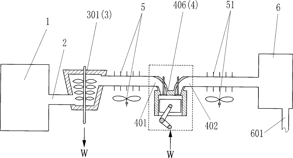
[0038] Such as figure 2The difference between the compressed exhaust self-cooling system shown in Embodiment 1 is that the exhaust heat power unit 3 is set as a power turbine 301, and the exhaust gas in the exhaust passage 2 of the heat power system passes through the power turbine 301 to the outside. After working to cool down, the first heat exhauster 5 exhausts and cools down, and then enters the air inlet 401 of the compressor. The compressor 4 is a piston compressor 406 . The expansion unit 6 is provided with a cold gas liquid-solid outlet 601 .

Embodiment 3

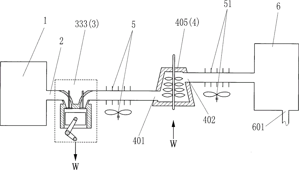
[0040] Such as image 3 The difference between the compressed exhaust self-cooling system shown in Embodiment 2 is that the exhaust thermal power unit 3 is set as a piston-type working mechanism 333, and the exhaust gas in the exhaust passage 2 of the thermal power system passes through the piston-type working mechanism. The power mechanism 333 works externally to cool down and then enters the air inlet 401 of the compressor after the first heat exhauster 5 exhausts heat and cools down. The compressor 4 is a turbo compressor 405 .


PUM


Abstract

A compression type exhaust self-cooling system includes a thermodynamic system (1), an exhaust passage (2), an exhaust thermodynamic unit (3), a gas compressor (4), a first heat radiator (5), a second heat radiator (51) and an expansion unit (6). The exhaust passage (2) of the thermodynamic system (1) is communicated with the gas inlet of the exhaust thermodynamic unit (3). The gas outlet of the exhaust thermodynamic unit (3) is communicated with the inlet for the gas to be cooled of the first heat radiator (5), and the cooled gas outlet of the first heat radiator (5) is communicated with the gas inlet (401) of the gas compressor (4). The compressed gas outlet (402) of the gas compressor (4) is communicated with the inlet for the gas to be cooled of the second heat radiator (51), and the cooled gas outlet of the second heat radiator (51) is communicated with the gas inlet of the expansion unit (6). The exhaust thermodynamic unit (3) outputs power or a compensatory power to the gas compressor (4). The system can realize the gas-closed cycle in a high efficiency, and reduce or eliminate the pollutant emission.

Description

technical field [0001] The invention relates to the field of thermal energy and power, in particular to a compressed exhaust self-cooling system. technical background [0002] In thermal power systems (such as engines, gas turbines, etc.), there are many situations where it is necessary to cool, liquefy or solidify the exhaust gas. For example, in order to recover the carbon dioxide in the exhaust gas, it is necessary to cool the exhaust gas and separate the water vapor in it before proceeding. Deep cooling, liquefaction or solidification of carbon dioxide. In some cases, such as to effectively recirculate the exhaust gas from the combustion chamber, it is also necessary to cool the exhaust gas. The temperature of the exhaust gas generally has a high temperature of seven to eight hundred degrees. The traditional method is to install a heat exchanger, but this method requires a large heat exchange area, and not only wastes the energy of the exhaust gas, but also needs to dis...

Claims


Application Information

Patent Timeline
Patent Type & Authority Patents(China)
IPC IPC(8): F02G1/043F02G1/055
CPCF02B29/0425F02B29/0481F02B39/005Y02T10/12
Inventor 靳北彪
Owner 张家港市乐余科创园投资发展有限公司
Learn More