Plunger hydraulic motor with automatical initiative input and driven state switchover

A hydraulic motor, plunger type technology, applied in the direction of variable capacity engine, machine/engine, reciprocating piston engine, etc., can solve the problems of increasing rotor resistance, turbulence, waste of energy, etc., to reduce resistance, reduce internal Loss and burden reduction effect

Active Publication Date: 2013-09-18
宁波恒通诺达液压股份有限公司
View PDF6 Cites 0 Cited by
  • Summary
  • Abstract
  • Description
  • Claims
  • Application Information

AI Technical Summary

Problems solved by technology

[0008] 1. When the plunger hydraulic motor is in the free wheel state, it is still necessary to maintain an external high-pressure oil supply to maintain the back pressure, so the equipment that provides oil circuit pressure must always be in working condition
[0009] 2. Due to the high pressure between the rotor and the stator of the plunger motor, the resistance of the rotor to rotate when it is driven is increased, wasting energy
[0010] 3. The reliability of back pressure is not high
As the motor speed increases, the centrifugal force of the plunger also gradually increases, and it is difficult to accurately adjust the oil pressure provided with the increase of the speed, so that the plunger cannot be stably kept at the bottom of the plunger hole, causing the roller at the front end of the plunger to be exposed The plunger hole, which then stirs the pressure oil between the rotor and the stator, forming a turbulent flow
Since the inner wall of the stator is often a multi-action inner curve structure, the turbulence of the pressure oil will further waste energy
Because there is high-pressure oil inside the plunger cavity, the contact between the roller and the inner wall of the stator becomes unreliable after the roller is extended. Unexpected bumps occur in the inner curve structure, which affects the service life of the hydraulic motor

Method used


Image

  • Plunger hydraulic motor with automatical initiative input and driven state switchover
  • Plunger hydraulic motor with automatical initiative input and driven state switchover
  • Plunger hydraulic motor with automatical initiative input and driven state switchover

Examples


Embodiment Construction

[0021] Embodiments of the present invention will be further described in detail below in conjunction with the accompanying drawings.

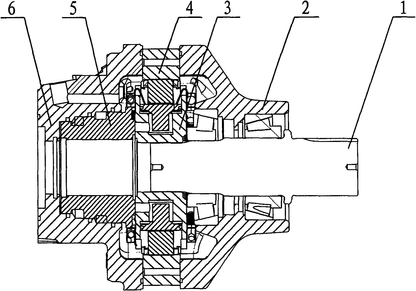
[0022] A plunger hydraulic motor, such as figure 1 As shown, it includes a front cover 2 , a rear cover 6 , a flow plate 5 , a stator 4 , a rotor 3 and a shaft 1 . The rear cover, distribution plate and stator are fixedly connected by bolts, the rotor is fixed on the upper rotating shaft, and the rotating shaft is connected to the front cover and rear cover through bearings, and then the front cover, stator, distribution plate and rear cover are fixed by bolts .

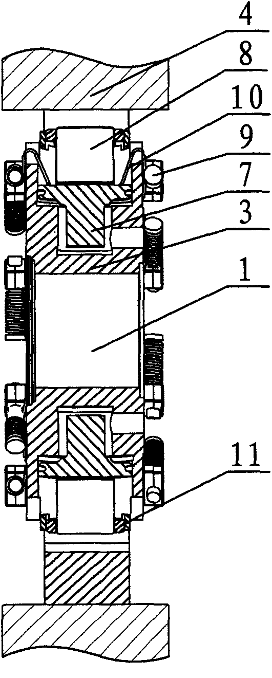
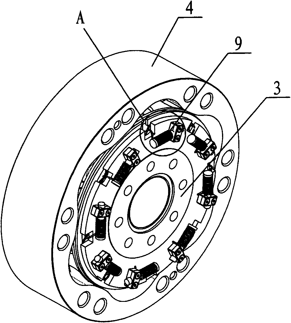
[0023] Such as figure 2 , image 3 , Figure 4 As shown, eight plunger holes 31 are evenly distributed on the rotor 3 , and a plunger 7 is installed in the plunger hole 31 , and the top of the plunger 7 is rotatably connected with the roller 8 . A retaining ring 11 is also installed on the plunger hole 31 to reduce the shaking when the roller 8 rotates.

[0024] There are also ...


PUM


Abstract

The invention relates to a plunger hydraulic motor with automatic initiative input and driven state switchover, and the plunger hydraulic motor comprises a front cover plate, a rear cover plate, a thrust plate, a stator, a rotor and a rotary shaft, wherein the rotor is uniformly provided with multiple plunger holes, plungers are installed in the plunger holes, the top of each plunger is rotatablyconnected with the roller, the top of each plunger hole is provided with a check ring, the two sides of the plunger hole on the rotor are respectively provided with a groove, the two sides of the rotor also are uniformly distributed with fixed blocks, a torsional spring is sleeved on each fixed block, and the front ends of the torsional springs pass through the grooves and are pressed on the topsof the plungers. When the plunger hydraulic motor is in a free wheel state, the plungers are pressed by the torsional springs, the phenomenon that the plungers and the roller break away from the plunger holes because of centrifugal force can be avoided, thus the high pressure between the rotor and the stator does not need to maintain, the burden of an oil-way is reduced, the resistance of the motor driven is reduced, and the inner loss is reduced; and when the motor initiatively inputs the torsion, the oil pressure in each plunger cavity is more than ten times the preload of the torsional springs, the influence on the motor acting is very small, and the motor is suitable for the occasion that power producer needs to be changed frequently.

Description

technical field [0001] The invention relates to a plunger-type hydraulic motor, in particular to a plunger-type hydraulic motor whose active output and driven state can be automatically switched. Background technique [0002] With the wide application of hydraulic systems in various industries such as machinery manufacturing, plunger hydraulic motors are often used as power output devices because of their high torque at low speeds and high efficiency. However, with the design requirements, the plunger hydraulic motor is no longer the only power source in the hydraulic system, and is often used in combination with other power devices such as electric motors and internal combustion engines or other hydraulic motors. For example, when the ship starts, a large torque force is required, and multiple hydraulic motors can work together, while in the smooth sailing stage, only one or part of the hydraulic motors are required to provide torque force. [0003] In addition, the plunge...

Claims


Application Information

Patent Timeline
Patent Type & Authority Patents(China)
IPC IPC(8): F03C1/013
Inventor 刘赟清
Owner 宁波恒通诺达液压股份有限公司
Why Eureka
Try Eureka