Multi-target location method of bistatic common-address multi-input-multi-output radar

A multi-target positioning and multi-input technology, which is applied in the direction of radio wave reflection/re-radiation, re-radiation, and measurement devices, can solve the problems of large amount of calculation, unfavorable real-time processing and hardware implementation, and low estimation accuracy. The effect of improving accuracy

Inactive Publication Date: 2011-10-12
HARBIN ENG UNIV
View PDF2 Cites 28 Cited by
  • Summary
  • Abstract
  • Description
  • Claims
  • Application Information

AI Technical Summary

Problems solved by technology

Since most of the above need to apply the MUSIC algorithm or ESPRIT algorithm principle to the transmitter and receiver at the same time to estimate the target’s launch angle and rece

Method used


Image

  • Multi-target location method of bistatic common-address multi-input-multi-output radar
  • Multi-target location method of bistatic common-address multi-input-multi-output radar
  • Multi-target location method of bistatic common-address multi-input-multi-output radar

Examples


Embodiment Construction

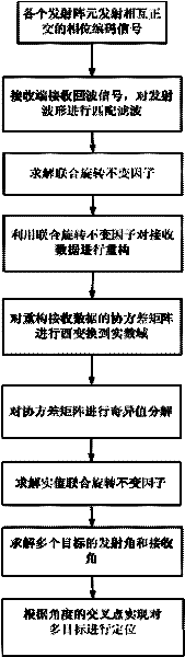
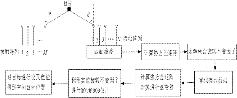
[0048] The technology of the target positioning method of the present invention mainly includes the following aspects:

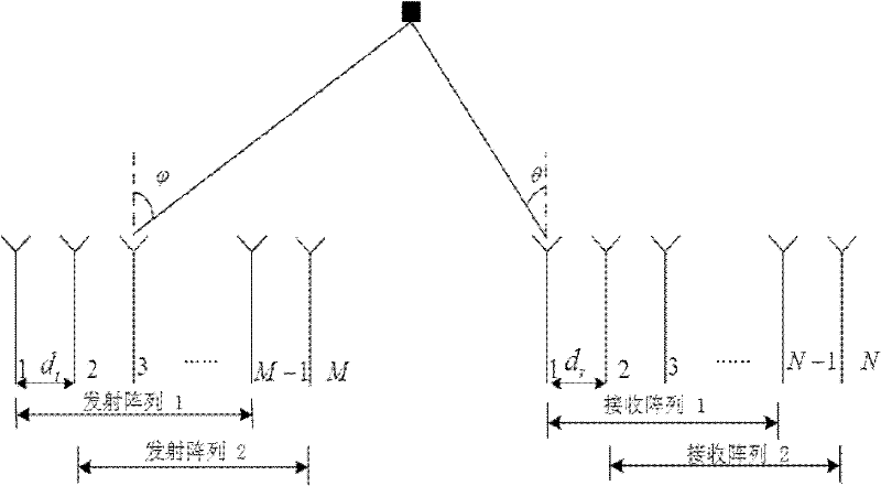
[0049] 1. Deriving the joint rotation invariant factor for MIMO radar

[0050] Such as figure 2As shown in , the MIMO radar consists of M transmitting array elements and N receiving array elements. Assuming that the MIMO radar is divided into two sub-MIMO radars, the first sub-MIMO radar is composed of a transmitting array 1 and a receiving array 1, and the second sub-MIMO radar is composed of a transmitting array 2 and a receiving array 2. Among them, the transmitting array 1 and the receiving array 1 are respectively composed of the front of the transmitting array and the receiving array Composed of array elements, the transmitting array 2 and receiving array 2 are respectively composed of the rear of the transmitting array and the receiving array composed of array elements.

[0051] The steering matrix of the first sub-MIMO radar is

[0052]

...


PUM


Abstract

The invention provides a multi-target location method of a bistatic common-address multi-input-multi-output radar. The method comprises the following steps of: transmitting mutual orthogonal phase coded signals by M transmitting array elements; receiving the phase coded signals by N receiving array elements; performing matching filtering on the received phase coded signals by a matching filter ofeach receiver which is used for receiving the array elements; reconfiguring covariance matrix of signal data subjected to matching filtering; performing unitary transformation on the reconfigured covariance matrix to obtain the covariance matrix of a real number field; performing singular value decomposition on the covariance matrix of the real number field; estimating emission angles and acceptance angles of a plurality of objects by utilizing actual value combination spinning invariant factor; and realizing multi-target location according to a cross point of the two angles to obtain the position of a space object. According to the method, the combination spinning invariant factor is adopted to reconfigure the receiving data so as to improve the estimation performance of an object; and the covariance matrix of the real number field is obtained through unitary transformation, and characteristic decomposition is performed on the covariance matrix of the real number field so as to be favorable for real-time processing and realization on hardware.

Description

technical field [0001] The invention relates to a radar target positioning technology, in particular to a multi-target positioning method for a multiple-input multiple-output co-location MIMO radar system. Background technique [0002] Multiple-input multiple-output (MIMO) radar is a new system radar with high detection performance and survivability based on the multiple-input multiple-output technology in the communication field. Compared with the traditional MIMO radar, MIMO radar transmits mutually orthogonal waveforms at the transmitting end, and can form a large virtual array aperture through matched filtering at the receiving end, which improves the spatial resolution of detecting targets. MIMO radar can use the widely distributed arrangement of array elements to obtain space diversity characteristics and suppress the shortcomings of target scintillation. At present, MIMO radar is mainly divided into the following two types. One is co-site MIMO radar. The array elemen...

Claims


Application Information

Patent Timeline
IPC IPC(8): G01S13/06G01S7/02
Inventor 王伟王咸鹏支红红李欣马跃华黄平薛冰郝燕玲赵俊杰
Owner HARBIN ENG UNIV
Why Eureka
Try Eureka