Valve current control method based on modular multi-level converter

A modular multi-level, control method technology, applied in the direction of converting irreversible DC power input to AC power output, converting AC power input to DC power output, and converting irreversible AC power input to DC power output, etc. Solve the problems of AC output voltage distortion, DC current distortion, increased loss of converter valve, etc., to achieve the effect of realizing bridge arm circulating current suppression, solving system oscillation, and reducing system loss

Active Publication Date: 2011-10-12
CHINA ELECTRIC POWER RES INST +1
View PDF4 Cites 28 Cited by
  • Summary
  • Abstract
  • Description
  • Claims
  • Application Information

AI Technical Summary

Problems solved by technology

[0008] The valve current of the modular multilevel converter consists of two parts, one is the AC current entered by the AC terminal, and the other is the DC current entered by the DC terminal. During the operation of the system, the capacitor voltage of the sub-modules of each bridge arm Not completely consistent, resulting in distortion of its AC output voltage, which will cause distortion of the DC current (generally referred to as the circulating current component) entering from the DC terminal. There are two general consequences. One is to cause the circulation of the bridge arm. Double frequency component; the second is to cause the current to appear unsteady low-frequency oscillation, and the double frequency harmonic component will increase the loss of the converter valve and seriously affect the transmission efficiency of the system

Method used


Image

  • Valve current control method based on modular multi-level converter
  • Valve current control method based on modular multi-level converter
  • Valve current control method based on modular multi-level converter

Examples


Embodiment Construction

[0041] The specific implementation manners of the present invention will be further described in detail below in conjunction with the accompanying drawings.

[0042] The valve current control of the modular multilevel converter can be divided into two control layers: the low-frequency oscillation control of the current and the double-frequency harmonic component control. The control schemes adopted are different, and the low-frequency oscillation of the current will be introduced separately below. control and double frequency harmonic component control.

[0043] 1. For the low-frequency oscillation of the current, it is divided into the oscillating circulating current between the bridge arms and the oscillating current between the two converters.

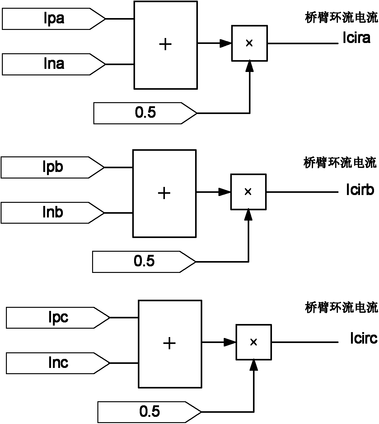
[0044] (1) The control steps of the oscillating circulation between the bridge arms are as follows:

[0045] image 3is the schematic diagram of the bridge arm circulation calculation method, such as image 3 As shown, first add ...


PUM


Abstract

The invention relates to a valve current control method based on a modular multi-level converter. In the method, valve current control is realized by a low-frequency oscillation control scheme for a current and a frequency doubling harmonic component control scheme for the current. The low-frequency oscillation control scheme for the current comprises the following steps of: calculating a half of the sum of currents of an upper bridge arm and a lower bridge arm to obtain a direct current component (namely a bridge arm ring current) in a valve; comparing an actual value of the bridge arm ring current with a set value of the bridge arm ring current to obtain an error; and carrying out signal processing to obtain an additional output voltage set value. The frequency doubling harmonic component control scheme for the current comprises the following steps of: calculating to obtain a capacitive voltage fluctuation pre-estimated value of a sub-module; and dividing the sum of a reference voltage pre-estimated value of the sub-module and a capacitive voltage pre-estimated value by the output voltage set value to obtain an actual sub-module output quantity set value. By the method, the stability of the dynamic performance of a system and the restraint on doubling harmonic components of the bridge arms are realized, and a valve current has excellent output characteristics under the abnormal working condition of an alternating system.

Description

technical field [0001] The invention relates to a control method in the field of flexible direct current transmission (VSC-HVDC), in particular to a valve current control method based on a modular multilevel converter. Background technique [0002] The flexible application performance of flexible DC makes it have extremely broad application prospects in the fields of urban power grid interconnection, new energy grid connection, and passive load power supply. Modular multilevel converters are a new type of The emergence of a converter suitable for the field of high-voltage flexible DC transmission technology breaks the original situation where the two-level topology monopolizes the flexible DC market, and broadens the options for flexible DC applications. [0003] Each bridge arm of the modular multi-level has the same number of sub-modules connected in series with the bridge arm reactance. By controlling the input and exit of the sub-modules, the output ground voltage is clo...

Claims


Application Information

Patent Timeline
Patent Type & Authority Applications(China)
IPC IPC(8): H02M7/12H02M7/217
CPCH02M1/14H02M7/483H02M1/0003H02M7/4835H02M7/44
Inventor 汤广福杨杰王姗姗孔明刘栋
Owner CHINA ELECTRIC POWER RES INST
Why Eureka
Try Eureka